
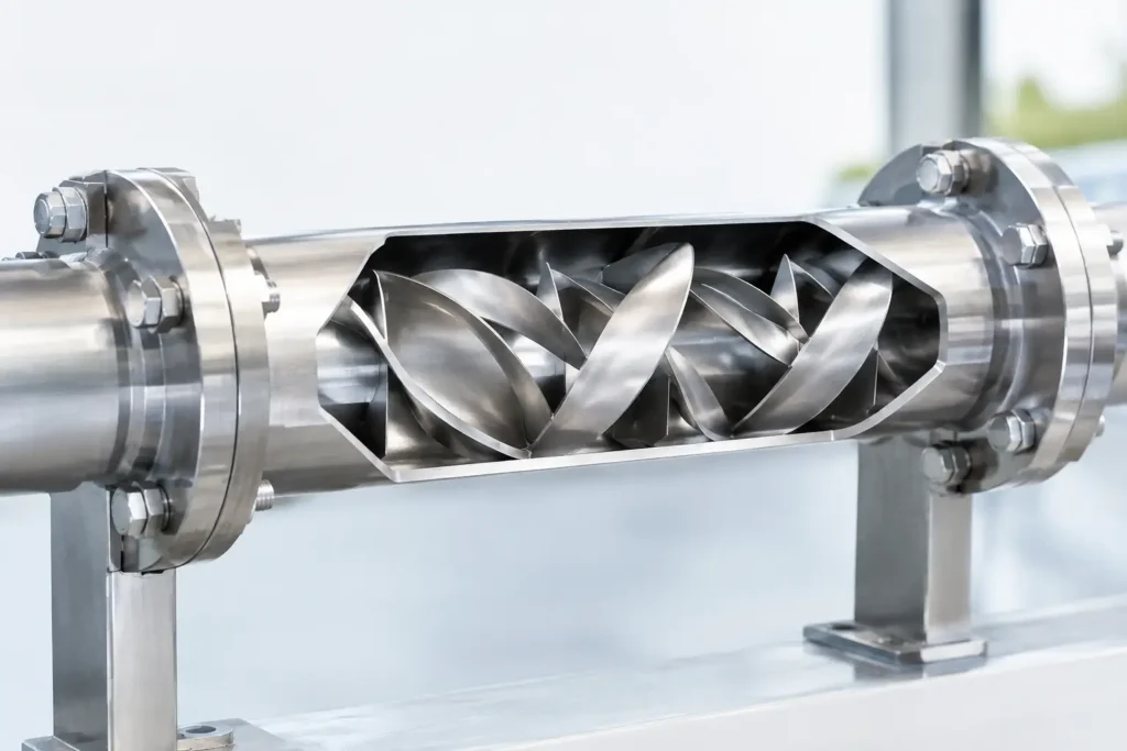
A static mixer can appear deceptively simple: a pipe housing containing fixed elements. Yet inline static mixer design has a direct effect on blend uniformity, chemical consumption, pressure drop, residence time, downstream equipment protection, and process reliability. The difference between a mixer that merely creates turbulence and one that consistently meets a concentration or reaction target is in the engineering behind the specification.
For industrial operators, the goal is not to select the longest mixer or the most aggressive element geometry. It is to achieve the required mixing result at the actual flow range, fluid properties, injection conditions, and allowable pressure loss of the system.
Start With the Required Mixing Result
A proper design begins with the process objective. “Mixing” can mean dilution of a chemical injection stream, blending two liquids of similar viscosity, dispersing an additive, promoting a reaction, equalizing temperature, or conditioning a flow profile ahead of a meter, analyzer, filter, or membrane system. Each duty calls for a different level of intensity.
The specification should identify the target concentration uniformity and the point in the process where that uniformity must be achieved. A disinfectant or pH-control chemical may need to be fully distributed before entering a contact tank. A polymer solution may need controlled incorporation without excessive shear. A gas-liquid application may require dispersion and contact area while avoiding an unacceptable pressure penalty.
This distinction matters because a mixer can produce an acceptable average sample while still allowing localized concentration variation. In chemical injection service, those pockets can cause poor treatment performance, corrosion, scaling, off-spec product, or unreliable analyzer readings.
The Flow Regime Drives Inline Static Mixer Design
The Reynolds number is central to inline static mixer design because it indicates whether the process is operating in laminar, transitional, or turbulent flow. It is influenced by fluid density, viscosity, flow velocity, and pipe diameter. The same mixer geometry can behave very differently when a process changes from water-like viscosity to a heavy oil, resin, slurry, or polymer solution.
In turbulent flow, static elements divide and redirect the stream, creating repeated changes in direction and radial mixing. Many liquid blending duties can reach high uniformity in relatively short installed lengths when velocity is sufficient and the injection point is properly located.
Laminar service is different. Viscous fluids do not naturally mix across the pipe radius simply because they travel through a length of pipe. Effective elements must repeatedly split, rotate, and recombine the flow to reduce striation thickness. This often requires more elements, more precise geometry, and a realistic review of pressure drop. A design that performs well with a low-viscosity solvent may be unsuitable for a high-viscosity adhesive at the same nominal flow rate.
Transitional flow deserves particular attention because it can shift with temperature, batch conditions, product formulation, or normal operating turndown. When performance must remain consistent across a broad flow range, specify the minimum, normal, and maximum operating cases rather than designing only around a single nominal flow.
Flow Rate Is More Than a Capacity Number
Minimum flow can be the limiting case for turbulent applications because lower velocity reduces mixing energy. Maximum flow may control pressure drop, erosion risk, noise, and mechanical loading. If a process cycles between low-flow startup and high-flow production, the mixer must be evaluated at both conditions.
Plant teams should also account for intermittent injection. A steady carrier stream with a pulsed dosing pump can create concentration spikes at the mixer inlet. The static mixer may homogenize those pulses, but its required length and injection arrangement should be based on the actual dosing profile, not an assumed continuous feed.
Select Element Geometry for the Duty
Static mixer elements are not interchangeable. Helical, corrugated, plate-style, and specialty geometries create different flow patterns, shear levels, pressure losses, and solids-handling characteristics. Element selection should follow the duty rather than catalog familiarity.
Helical elements are widely used for liquid-liquid blending, chemical dilution, viscosity-sensitive applications, and laminar mixing. Their repeated flow division supports predictable blending across a broad range of viscosities. More aggressive geometries can deliver higher shear for dispersion and emulsification, but they also increase pressure drop and may not suit shear-sensitive materials.
For solids-bearing or fouling service, open geometries and appropriate housing diameters can reduce plugging risk. A narrow, high-intensity element may achieve excellent mixing in a clean process but create an unacceptable maintenance point when fibers, crystals, scale, or suspended solids are present. In sanitary processes, cleanability, surface finish, drainability, and connection design must be considered alongside mixing performance.
A useful specification does not simply state “static mixer.” It identifies the fluid pair, viscosity range, desired blend quality, acceptable pressure loss, solids content, cleaning requirements, and material compatibility. That gives the mixer supplier the information needed to select an element configuration that serves the process rather than forcing the process to fit the hardware.
Treat Pressure Drop as a Design Variable
Every static mixer creates pressure loss. That loss is not automatically a problem, but it must be calculated as part of the system rather than discovered after installation. The available pressure from a transfer pump, the pressure sensitivity of downstream equipment, and the total line loss all matter.
Increasing the number of elements generally improves mixing, but it also raises pressure drop. Reducing the mixer diameter can increase velocity and mixing intensity, yet it may create an excessive pressure requirement or limit future throughput. Enlarging the housing can lower pressure loss, though velocity may fall enough to reduce performance in turbulent service.
The best design is often a balance between installed length, diameter, element count, and pump capability. It depends on the process. A short, high-intensity mixer can be the right choice where space is limited and differential pressure is available. A larger-diameter, lower-loss design may be better for gravity-fed systems, low-head pumps, or processes with expensive energy costs.
Injection Location Can Make or Break Performance
A static mixer cannot correct every poor injection arrangement. The secondary stream must enter the carrier stream in a way that provides a reasonable starting distribution before it reaches the first element. Injecting directly against a pipe wall, into a stagnant zone, or immediately upstream of a poorly positioned elbow can compromise the expected result.
Injection quills are often the right solution for chemical dosing because they position the injection point in the active flow stream. Quill design should consider insertion depth, backpressure, check-valve placement, material compatibility, and the potential for precipitation or buildup at the tip. For reactive chemicals, the distance between injection and mixing should be minimized so the chemical does not contact pipe surfaces in concentrated form longer than necessary.
For multiple additives, staged injection may be required. Combining incompatible chemicals at a common injection point can create unwanted reactions, deposits, gas release, or safety hazards before the mixer has an opportunity to distribute them.
Match Materials and Connections to Real Service Conditions
Material selection is a process decision, not a default preference. Stainless steel is suitable for many industrial fluids, but chlorides, oxidizers, acids, caustics, solvents, high temperatures, and sanitary requirements may call for a different alloy, polymer, fluoropolymer-lined construction, or specialty material.
PVC, CPVC, PVDF, PFA, and lined mixer assemblies can provide valuable corrosion resistance in chemical service. Specialty alloys may be necessary when temperature, pressure, or corrosive exposure exceed the limits of standard materials. The housing, elements, flanges, gaskets, injection assembly, and wetted instrumentation connections should all be reviewed as one system.
Connection requirements matter as well. Flanged, threaded, sanitary clamp, socket weld, butt weld, and custom end connections each affect installation, maintenance, pressure rating, and cleanability. A ready-to-ship mixer is valuable only if it integrates correctly with the piping standard already used in the plant.
Validate the Design Before Fabrication
For critical applications, design validation should go beyond a rule-of-thumb element count. Process data, pressure-drop calculations, flow modeling, and application review can confirm whether the selected mixer will meet the required coefficient of variation or mixing index at defined operating conditions.
Provide the actual process envelope: minimum and maximum flow, viscosity at process temperature, density, pressure, temperature, line size, additive flow rate, required materials, allowable pressure loss, and any solids or gas content. If product quality, regulatory compliance, or safe chemical injection depends on uniformity, include the required performance target and available straight-run piping.
ProMixUSA engineers complete static mixing systems around those operating realities, from individual mixing elements and custom housings to injection quills and skid-mounted assemblies. The strongest result comes from treating the mixer as part of the process train, not as an isolated pipe component.
A well-specified static mixer earns its place quietly: it delivers repeatable blending, protects downstream operations, and keeps the process on target shift after shift.