
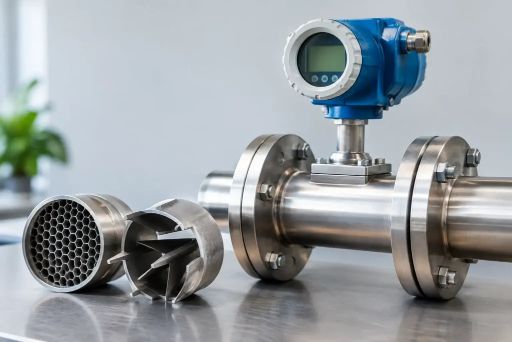
A meter can be correctly sized, correctly installed, and still deliver unreliable data when the flow entering it is distorted. A flow conditioner for flow meters is installed upstream to reduce swirl and establish a more repeatable velocity profile before fluid reaches the meter. For plants tracking chemical dosage, custody transfer, batch consistency, utility consumption, or compliance-critical flow rates, that stability can protect far more than a single measurement point.
The need usually appears after a piping layout becomes more compact or more complex. A pump discharge, control valve, elbow, reducer, tee, strainer, partially open valve, or temporary bypass can disturb the fluid profile entering a meter. The result may be drift, poor repeatability, unexplained differences between instruments, or a meter that performs well during commissioning but not under normal operating conditions.
Why Flow Meters Need Conditioned Flow
Most flow meter technologies are calibrated or specified against defined inlet conditions. The meter does not simply measure a nominal pipe velocity. It responds to the velocity distribution, turbulence level, pressure profile, and, in some cases, swirl within the pipe.
Swirl is particularly troublesome because fluid rotates around the pipe axis while moving downstream. A single elbow can create some asymmetry. Two elbows in different planes, a close-coupled pump, or a control valve can create stronger and more persistent disturbances. These conditions may cause different regions of the meter to see substantially different velocities than the instrument expects.
A flow conditioner does not make every installation identical to a laboratory test section. Its purpose is more practical: it reduces the influence of upstream disturbances so the meter receives a stable, repeatable flow profile within a manageable straight-run distance. That can help plants meet meter manufacturer installation requirements where long lengths of straight pipe are unavailable.
The value is not limited to meter accuracy. Reliable flow data supports stable chemical injection, better batch control, lower overfeed risk, more meaningful pump performance analysis, and faster troubleshooting. When a meter is used as the control signal for a dosing system, a small measurement error can become a material quality or safety issue downstream.
Selecting a Flow Conditioner for Flow Meters
The correct selection starts with the meter technology, not with pipe size alone. Magnetic, ultrasonic, turbine, vortex, Coriolis, differential-pressure, and positive displacement meters respond differently to inlet effects. Some technologies tolerate disturbances better than others, while some require carefully defined upstream and downstream piping geometry.
A Coriolis meter, for example, generally has less sensitivity to velocity profile than an insertion device or many differential-pressure configurations. That does not mean upstream piping never matters. Two-phase flow, cavitation, flashing, vibration, or an unstable pump discharge can still compromise performance. A turbine meter or differential-pressure meter may be much more dependent on a developed profile and can benefit significantly from a properly designed conditioner.
The upstream disturbance must also be identified. An elbow, a valve, and a pump do not create the same flow pattern, so they should not be treated as equivalent. A conditioner placed after a control valve may need to handle strong turbulence and variable flow conditions. One installed after a centrifugal pump may be selected primarily to reduce swirl and asymmetry. Where multiple disturbances are close together, the complete piping arrangement deserves review rather than a quick rule-of-thumb purchase.
Straight Pipe Is Helpful, but Not Always Available
Straight pipe allows disturbed flow to redevelop naturally. In a new installation with ample space, additional straight run can be the simplest solution. In skid-mounted systems, retrofit projects, crowded utility racks, and packaged OEM equipment, that space is often unavailable.
A flow conditioner can reduce the required straight-run distance, but it does not eliminate installation requirements. The conditioner itself needs the correct location, orientation where applicable, and suitable spacing from the meter. Downstream requirements also matter for many meter types, especially where pressure recovery, valves, or changing pipe geometry could influence the reading.
The practical question is not, “Can a conditioner replace all straight pipe?” It is, “What piping arrangement will provide repeatable measurement performance for this meter and process?” That answer depends on the meter manufacturer’s recommendations, the severity of the disturbance, and the acceptable uncertainty for the application.
Common Conditioner Designs and Their Trade-Offs
Flow conditioners are available in several internal geometries, including tube bundles, perforated plates, multi-hole designs, and engineered vane-style configurations. Each design works by redistributing momentum through the pipe and reducing the larger-scale rotational or asymmetric components of the flow.
A tube-bundle style can divide the stream into many smaller passages, helping reduce swirl and establish a more uniform profile. Multi-hole and perforated-plate designs can provide effective conditioning in shorter installations, depending on geometry and service conditions. Engineered designs may be chosen when a particular meter standard, pipe arrangement, or performance target applies.
Pressure drop is the central trade-off. A more aggressive internal geometry may provide stronger conditioning, but it also consumes available pressure. In a low-pressure system, a gravity-fed line, or a process near pump limits, that added loss may be unacceptable. In high-viscosity service, pressure drop can increase further and must be evaluated under actual operating temperatures and flow rates.
Fouling is another selection issue. A conditioner with small passages may not be appropriate for fluids containing fibers, solids, scale, wax, polymer buildup, or crystallizing chemicals. For sanitary or high-purity service, cleanability, drainability, surface finish, and material certification may be as important as the conditioning effect. A poorly matched conditioner can create a maintenance point that offsets its measurement benefit.
Materials and Connections Must Match the Process
The wetted materials must tolerate both the process fluid and the cleaning or flushing chemicals used around it. Stainless steel is a common choice for water, many chemicals, food processing, and general industrial service. PVC, CPVC, PVDF, PFA-lined designs, specialty alloys, and sanitary materials may be required for corrosive chemicals, elevated temperatures, high-purity applications, or aggressive cleaning programs.
Connection choice also affects installation quality. Flanged units are common in industrial process piping because they support controlled alignment and easier removal for inspection. Sanitary clamp connections can be appropriate where hygienic design and fast disassembly are required. Threaded or custom connection arrangements may be suitable for smaller lines and OEM packages, provided the system layout can maintain concentric alignment and prevent leaks.
The conditioner bore, flange rating, gasket selection, and face-to-face dimension should be reviewed as a package. Reducing a line immediately before the conditioner, using an eccentric transition in the wrong orientation, or installing a mismatched gasket can introduce a new disturbance immediately upstream of the meter.
Installation Details That Protect Measurement Performance
Install the conditioner according to its specified flow direction. This sounds basic, but field retrofits often involve reused components, reversed spools, or unclear markings. Orientation is especially important for designs with directional internal elements.
Keep the pipe bore aligned through the conditioner and meter. Internal steps, protruding gaskets, weld intrusion, and misaligned flange faces can disturb the very profile the conditioner is intended to improve. For liquid lines, maintain operating conditions that prevent air entrainment, flashing, and partially full pipe where the meter requires full-bore flow.
For gas service, account for pressure, density variation, pulsation, and the potential for condensate. A conditioner may improve profile quality, but it will not correct a meter installed where liquid accumulates, pressure is unstable, or compressor pulsation dominates the signal.
Commissioning should include more than verifying that fluid moves through the line. Compare readings against a credible reference where practical, document the upstream piping configuration, and record normal flow ranges and pressure drop. If the meter is used for critical control or reporting, establish a verification schedule based on the consequences of error rather than waiting for a process upset.
When a Custom Flow Conditioning Solution Makes Sense
Standard configurations work well for many applications, particularly when line sizes, materials, pressure ratings, and meter requirements are conventional. Custom engineering becomes valuable when the piping is unusually constrained, the fluid is difficult, or the meter feeds a high-consequence control loop.
Examples include corrosive chemical injection systems, high-viscosity additives, sanitary blending lines, compact meter skids, gas systems with pulsation concerns, and large-diameter process headers. A custom solution may combine the conditioner with a static mixer, injection quill, spool piece, instrumentation ports, or specialized end connections. That approach can reduce field fabrication and place each component at the correct location from the start.
ProMixUSA supports flow-conditioning equipment with application-specific materials, connection options, and custom fabrication for demanding process layouts. The best specification begins with real operating data: fluid properties, flow range, pressure and temperature, line size, meter type, nearby piping components, available straight run, allowable pressure loss, and required measurement confidence.
A flow conditioner is not a substitute for sound piping design or a cure for every meter problem. It is a focused tool for controlling inlet conditions when accurate flow data matters and the process line cannot be treated as an ideal test section. Specify it around the actual disturbance, meter, and process objective, and it becomes a practical way to keep measurement performance predictable as the plant operates.