
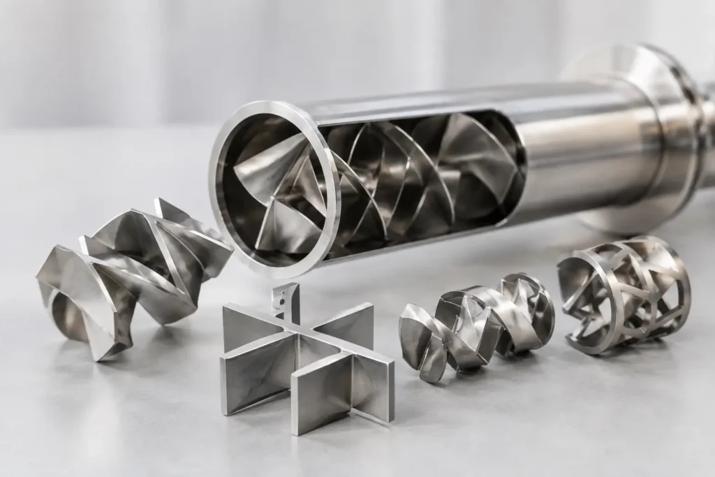
A static mixer can be correctly sized on paper and still underperform if its internal geometry is wrong for the fluid, injection point, or operating range. Custom static mixer elements address that gap. Rather than treating the mixer as a standard pipe spool, they tailor the internal mixing path to the actual process conditions that determine blend quality, pressure drop, residence-time distribution, and cleanability.
For process engineers, OEMs, and plant teams, that distinction matters when product consistency, chemical utilization, or safe injection cannot depend on a narrow flow window. The right element design creates repeatable splitting, rotation, radial transport, and recombination of the process stream without motors, seals, or moving parts.
What Custom Static Mixer Elements Change
A conventional inline static mixer uses fixed internal elements to divide and redirect flowing material. Each element increases the number of fluid layers and reduces the distance over which components must diffuse. In turbulent flow, the geometry promotes rapid radial mixing through repeated changes in flow direction. In laminar flow, where turbulence cannot do the work, the elements continuously rearrange the fluid to create the thin layers required for effective blending.
Custom static mixer elements change more than diameter or length. Their geometry, element count, pitch, leading-edge configuration, open area, and orientation can be selected around the duty. That lets an engineered mixer solve for a specific balance of mixing intensity and pressure loss instead of forcing a difficult application into a catalog configuration.
This is especially valuable when a process has one or more limiting conditions: a high-viscosity carrier, a low-dose additive, a corrosive chemical, a short available straight run, a sanitary requirement, or large changes in flow rate. A mixer that performs well at its nominal design point may be a poor choice if the line regularly operates at 40 percent capacity or experiences intermittent dosing.
Start With the Process, Not the Element Shape
The element family should follow the process objective. A compact, high-energy design may be appropriate for liquid-liquid blending, gas dispersion, or emulsification where fine distribution is the priority. A lower-pressure-drop geometry can be the better fit for dilution, pH adjustment, polymer addition, or flow conditioning where pumping capacity is limited.
The required data should include normal, minimum, and maximum flow rates; fluid viscosities and specific gravities; temperature and pressure; allowable pressure drop; solids content; and the physical properties of each injected stream. Injection details are equally important. The location, angle, velocity, and nozzle design of an injection quill can determine whether the additive reaches the mixer as a coherent stream, wall film, spray, or partially dispersed phase.
A strong specification also identifies what “mixed” means in measurable terms. That may be a concentration uniformity at a downstream sample point, a target pH range, reduced chemical consumption, stable viscosity, a controlled reaction profile, or elimination of visible streaking. Without a performance target, it is easy to specify a mixer that looks substantial but does not provide enough mixing duty.
Flow Regime Drives the Mixing Mechanism
Reynolds number provides a useful first indication of how the system will behave. Low-Reynolds-number flow is dominated by viscosity and requires a geometry that repeatedly divides and reorients the material. High-viscosity adhesives, oils, resins, coatings, food products, and polymer solutions often fall into this category. More elements or a longer mixing path may be needed, but the resulting pressure drop must remain within the capability of the pump and upstream equipment.
Turbulent flow presents a different design problem. The fluid is already moving energetically, but a poorly designed injection point can leave unmixed pockets or produce uneven concentration profiles. Custom geometry may focus on distributing an injected chemical rapidly across the pipe diameter while avoiding excessive pressure loss or localized erosion.
Many industrial systems operate between these two extremes. Transitional flow is where assumptions are most likely to fail. Modeling or mixer simulation can help determine whether a proposed element arrangement will maintain performance across the full operating envelope rather than only at a single flow condition.
Geometry, Length, and Pressure Drop Must Work Together
Every static mixer creates pressure drop. It is not a defect – it is the hydraulic cost of redirecting flow and generating mixing. The design objective is to spend that pressure drop where it produces useful mixing, not to add restriction without improving uniformity.
Element length and quantity affect both outcomes. Adding elements generally improves homogeneity, particularly for difficult laminar-flow duties, but also increases pressure loss. A larger mixer diameter may reduce velocity and pressure drop, yet it can weaken the mixing action if velocity falls too far. Conversely, reducing diameter can increase shear and improve dispersion while creating an unacceptable pumping requirement.
The available installation length is another practical constraint. A custom element assembly can be configured for a limited spool length, a removable cartridge, or a housing that supports maintenance access. For retrofit projects, the center-to-face dimension, flange standard, line orientation, and nearby valves or instruments should be evaluated before finalizing the design.
A mixer that is easy to install but impossible to inspect can create long-term maintenance risk. Processes with scaling, crystallization, fibrous solids, or fouling components may need a more open geometry, access ports, removable elements, or a clean-in-place approach. The most aggressive mixing pattern is not always the most reliable selection.
Material Selection Is Part of Mixer Performance
The element material must withstand the full chemical and temperature profile, including cleaning chemicals, startup conditions, and potential upsets. Stainless steel is widely used for general industrial and sanitary service, but it is not a universal solution. Chlorides, strong acids, caustics, oxidizers, and elevated temperatures can change the appropriate alloy or require a polymer, fluoropolymer, lined construction, or specialty metal.
Custom static mixer elements can be fabricated in 304 or 316 stainless steel, sanitary finishes, PVC, CPVC, PVDF, PFA, and specialty alloy constructions when the process demands it. Material choice affects more than corrosion resistance. Surface finish influences cleanability and product hold-up. Wall thickness and fabrication method affect structural stability at pressure. Polymer elements can offer broad chemical compatibility and lower weight, while metallic elements may be better suited to elevated temperature, vacuum, high pressure, or abrasive service.
For food, beverage, pharmaceutical, and other sanitary applications, cleanability should be defined early. Crevice-free fabrication, drainability, polished surfaces, sanitary connections, and CIP compatibility may be central requirements rather than optional features. A design intended for general chemical service should not be assumed to meet sanitary process expectations.
Injection and Mixing Should Be Engineered as One System
A static mixer cannot fully correct a poor injection arrangement. If the injected stream hugs the pipe wall, enters at insufficient velocity, or is introduced immediately upstream of an elbow, the mixer must overcome an unfavorable starting condition. That can require extra elements, raise pressure drop, and still leave variability at the downstream point of use.
The injection quill, nozzle, and static mixer should therefore be treated as a single system. For chemical dosing, a retractable or fixed quill can place the chemical in the highest-velocity region of the line and protect the pipe wall from concentrated chemicals. For reactive services, the injection point may need to minimize contact time before full dispersion. For gas-liquid duties, the injector must introduce the gas in a form the element geometry can distribute without causing unacceptable backpressure.
ProMixUSA applies this system-level approach when specifying complete static mixing assemblies, combining custom elements with housings, injection hardware, and connection options matched to the installation.
When Standard Elements Are Enough – and When They Are Not
Standard elements are often the right commercial choice for stable, well-understood duties with compatible materials, adequate line length, and modest performance requirements. They can be economical, readily available, and effective when the process closely matches their published operating range.
Customization becomes more valuable when the consequences of poor mixing are expensive. Consider chemical overfeed caused by inconsistent dilution, off-spec product from incomplete blending, corrosion at the injection point, excess pump energy, or shutdowns caused by fouling. In these cases, the initial savings from a generic internal design can disappear quickly.
Custom work does not have to mean an unnecessarily complex or long-lead solution. Often, it means selecting a proven element style and adjusting the details that control actual field performance: material, quantity, housing dimensions, connection type, injection arrangement, or removable construction. The best approach depends on whether the process problem is hydraulic, chemical, mechanical, sanitary, or all of the above.
Specify for Repeatable Results
A useful mixer inquiry gives the engineering team enough information to evaluate the full duty rather than simply quote a nominal pipe size. Include the process fluid data, flow range, line size, operating pressure and temperature, allowable pressure drop, injected chemical details, required downstream mixing quality, materials requirements, and connection preferences. If available, provide piping drawings, available straight-run dimensions, pump information, and records of existing mixing problems.
That information supports a design that can be tested against the actual operating conditions. It also makes it easier to identify whether a static mixer is the best solution or whether the process needs a different injection method, a mechanical mixer, a high-shear device, or additional residence time.
The most productive next step is to define the process variable that must remain stable downstream of the mixer. Once that target is clear, custom element geometry becomes a practical engineering tool rather than a specification guess.