
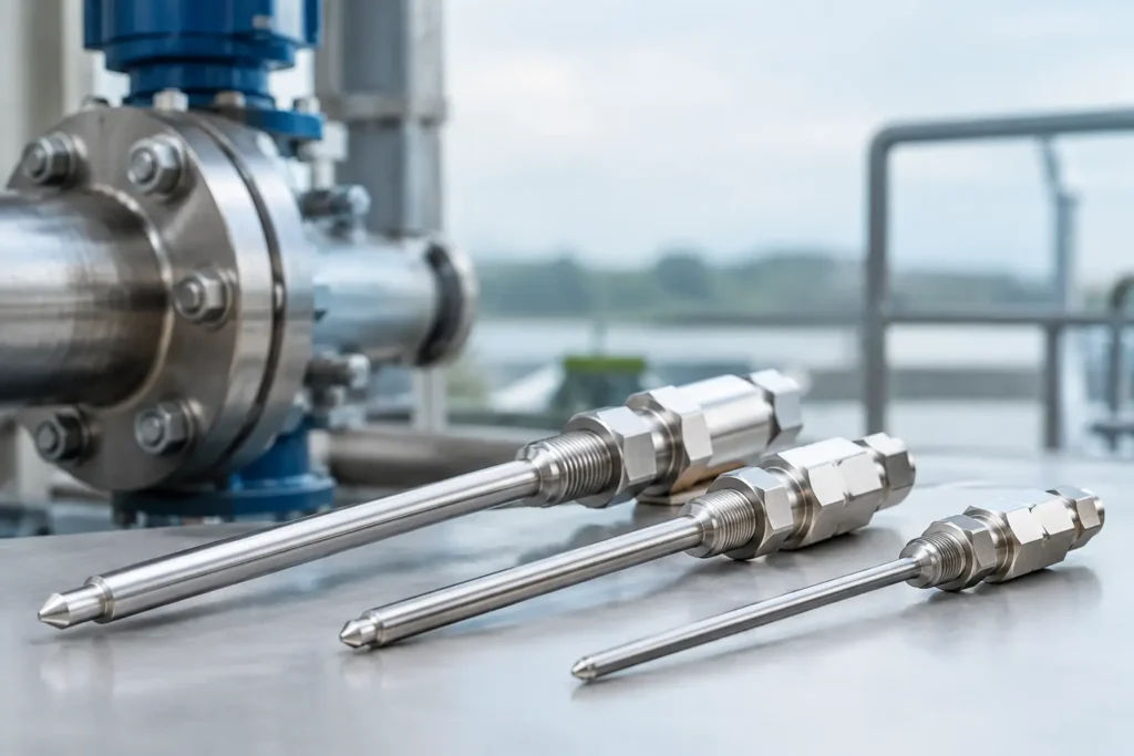
A fixed chemical injection quill is a small piping component with an outsized effect on chemical dosing accuracy, asset protection, and operator safety. When the injected chemical reaches the pipe wall, remains concentrated in a low-velocity zone, or enters a poorly selected location, the result can be corrosion, scaling, incomplete reaction, and avoidable chemical consumption. The quill establishes where and how the chemical enters the process stream so the downstream system can perform as designed.
For continuous, well-defined service, a fixed quill is often the most direct solution. It has no withdrawal mechanism, fewer moving parts, and a permanent insertion depth that supports repeatable injection conditions. The right design, however, depends on much more than line size and connection type.
What a Fixed Chemical Injection Quill Does
A fixed injection quill carries a chemical feed from the pipe connection into the flowing process stream. Rather than discharging chemical immediately at the pipe wall, the quill extends the injection point to a selected location within the pipe cross-section. This helps reduce wall wetting and puts the chemical where process velocity and turbulence can begin dispersing it.
Typical applications include corrosion inhibitor, biocide, coagulant, polymer, pH adjustment chemical, oxidizer, antiscalant, catalyst, and disinfectant injection. The service may involve water treatment, oil and gas, chemical processing, food and beverage, power generation, pulp and paper, and OEM treatment skids.
The quill is not a mixer by itself. Its purpose is controlled introduction. If the process requires a defined concentration profile within a short downstream distance, the quill should be paired with adequate pipe run, a static mixer, or another verified mixing method. Treating injection and mixing as separate design decisions is a common reason systems underperform.
Fixed vs. Retractable Injection Quills
A fixed quill is permanently installed through a threaded, flanged, welded, sanitary, or custom process connection. It is a strong fit when the injection point does not need to be removed while the line is pressurized and when scheduled shutdown access is acceptable. Its straightforward construction can reduce maintenance requirements and eliminate the added complexity of a retrieval assembly.
A retractable quill is better suited to services where the injection tube may foul, erode, or require inspection without taking the process line out of service. It can also be appropriate for high-pressure systems where removal must be controlled through an isolation and retrieval arrangement.
Neither option is automatically better. Fixed quills favor simplicity, repeatability, and lower installed complexity. Retractable designs favor service access and operational flexibility. The correct choice depends on chemical behavior, maintenance philosophy, operating pressure, and the consequences of taking the line offline.
Start With Process Conditions, Not a Standard Drawing
A quill that fits the nozzle can still be wrong for the application. Effective specification begins with actual operating data, including normal and maximum line pressure, line temperature, process fluid composition, chemical concentration, injection rate, pipe material and schedule, and available downstream mixing length.
Injection pressure deserves particular attention. The chemical feed system must overcome process-line pressure plus the pressure losses across tubing, fittings, check valves, quill passages, and any static mixer or downstream restriction. A marginal pressure differential can produce inconsistent dosing, reverse flow risk, or a check valve that does not reliably seat.
The injected fluid's physical properties also matter. A low-viscosity acid behaves very differently from a viscous polymer or slurry. Viscous chemicals may require a larger internal passage, higher feed pressure, heat tracing, or a different injection arrangement to prevent buildup. Chemicals that crystallize, polymerize, or generate solids may require flushing provisions and a quill geometry selected for cleanability rather than minimum cost.
For a complete engineered review, provide these details to the equipment supplier:
- Process fluid and injected chemical, including concentration and compatibility information
- Normal, minimum, and maximum flow rates, pressures, and temperatures
- Pipe size, schedule, material, orientation, and available connection type
- Injection flow rate range and feed-pump discharge pressure
- Required mixing quality and distance to the next critical process point
- Maintenance access, hazardous-area requirements, and cleaning or flushing needs
This information allows the quill length, material, wall thickness, tip configuration, and connection to be selected around the actual service rather than an assumption.
Quill Placement Controls Chemical Distribution
The injection tip should enter a region of meaningful process velocity without creating a direct path for chemical to strike the opposite pipe wall. In many applications, extending toward the pipe centerline improves initial contact with the moving stream. That is not a universal rule. A centerline location can be unsuitable where solids, fibrous materials, large debris, or certain multiphase flow patterns create plugging or vibration concerns.
Flow direction also matters. An injection tip may discharge with the process flow, across the stream, or at a selected angle based on the chemical, pipe geometry, and mixing objective. Cross-stream injection can improve initial dispersion in some liquid applications, while an incorrectly directed discharge can increase tip wear or create unstable backpressure. The discharge geometry should be evaluated with the operating velocity, not chosen solely because it is commonly stocked.
Avoid placing the quill immediately upstream of a dead leg, a low-flow branch, or a component that can collect concentrated chemical. Likewise, do not assume that a nearby elbow will provide dependable mixing. Elbows can generate turbulence, but their mixing performance changes with flow rate, pipe geometry, and fluid properties.
When uniform distribution is critical, install a static mixer downstream of the injection point. A properly sized static mixer divides and recombines the streams repeatedly, delivering predictable mixing performance across the stated operating range. ProMixUSA can engineer the quill and static mixing system together, which prevents a well-built injection point from being paired with an undersized or poorly located mixer.
Materials Must Handle Both Chemical Exposure and Process Reality
Material selection begins with chemical compatibility, but it cannot end there. The quill must also withstand line pressure, temperature, flow-induced vibration, external environment, cleaning chemicals, and the mechanical demands of the selected connection.
Stainless steel is widely used for general industrial service, but chloride exposure, strong acids, and elevated temperatures can require a higher-alloy material. PVC, CPVC, PVDF, PFA, and lined constructions can offer excellent resistance in corrosive chemical service, provided their temperature and pressure limits match the process. Sanitary applications may require polished stainless construction, sanitary connections, and a design that avoids product hold-up.
A chemical may be compatible with the quill tube but incompatible with the wetted components upstream. Check valves, seals, adapters, tubing, calibration columns, and feed-pump components should be reviewed as one wetted system. One overlooked elastomer or spring material can become the first failure point.
Pressure Integrity, Check Valves, and Safe Service Access
The quill connection must be rated for the complete pressure and temperature envelope, including startup, upset, and pump deadhead conditions where applicable. Threaded connections may be practical for smaller lines and utility service, while flanged, welded, or sanitary connections may be preferred for higher pressure, larger pipe sizes, regulated service, or maintenance requirements.
A suitable check valve near the injection point helps prevent process fluid from migrating backward into the chemical feed line. Its cracking pressure, materials, and response must match the application. A check valve is not a substitute for sound isolation design, especially where the process fluid is hazardous or where contamination of the chemical system creates a serious risk.
Consider how the quill will be isolated, depressurized, flushed, and inspected before finalizing the installation. A fixed quill is simple once installed, but it still requires safe access during turnarounds. In corrosive or toxic service, the piping layout should support controlled draining and minimize trapped chemical.
Specify for Repeatable Performance
The best fixed quill installations are treated as part of the process, not as an accessory added after the piping layout is complete. Define the operating envelope, identify the required downstream concentration uniformity, and select the insertion depth and tip orientation around real flow conditions.
A correctly engineered fixed chemical injection quill keeps the chemical where it belongs: in the moving process stream, entering at a controlled point, with materials and pressure capability matched to the service. That discipline protects equipment, reduces waste, and gives operators a dosing system they can rely on shift after shift.