
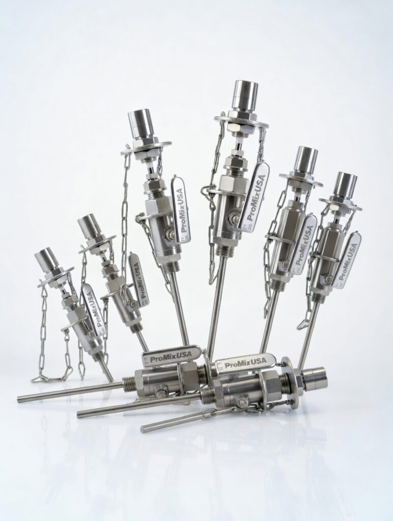
A chemical feed pump can deliver the correct volume and still produce an unreliable process result. The failure point is often where the chemical enters the line. Injection equipment determines whether a treatment chemical reaches the intended stream, disperses at the right rate, avoids damaging pipe components, and remains accessible for inspection. For plants handling corrosive chemicals, high-pressure process lines, variable flow, or strict product-quality targets, that point of entry deserves engineering attention.
A complete injection arrangement is rarely just a quill. It may include the metering pump, injection quill, isolation valve, check valve, calibration column, static mixer, instrumentation, and controls needed to verify delivery. The right configuration depends on the chemical, the main-line process conditions, and what must happen after the injection point.
Start With the Injection Duty
The first selection question is not which quill material is available. It is what the injected fluid must accomplish. Some applications require pH adjustment, corrosion control, disinfection, polymer activation, neutralization, oxidation, or nutrient dosing. Others introduce colorants, catalysts, fragrances, coagulants, antifoams, or cleaning chemicals. Each duty places different demands on the injection point and downstream mixing section.
Define the chemical concentration, normal and maximum feed rate, process flow range, line pressure, temperature, viscosity, and specific gravity. Also identify whether the chemical can gas off, crystallize, shear degrade, polymerize, or react quickly with the carrier fluid. A sodium hypochlorite system, for example, requires different materials and venting considerations than a viscous polymer feed or concentrated sulfuric acid service.
The main process flow profile matters as much as pump capacity. At low velocity, a chemical entering through a basic pipe tap can travel along the wall with limited dispersion. At high velocity, the injection point may see vibration, erosion, pressure effects, and greater forces on a retractable assembly. If operating flow changes substantially, equipment should be evaluated at minimum, normal, and maximum conditions rather than at one design flow.
Injection Equipment Is a System, Not a Single Component
An injection quill places the chemical stream into a controlled location within the process pipe. Fixed quills are a practical choice when line access is stable and the process allows a permanent insertion length. Retractable quills allow removal and servicing while the main line remains in operation when isolation and safety requirements are properly addressed. They are particularly valuable where deposits, scale, or chemical buildup make routine inspection necessary.
The insertion point should be selected to prevent the chemical from repeatedly contacting the pipe wall at high concentration. Direct wall impingement can accelerate corrosion, create localized deposits, or damage linings. In many services, positioning the outlet near the active flow region improves early dispersion. The best location still depends on velocity profile, pipe diameter, injection direction, and whether a downstream static mixer is installed.
Check valves are essential for preventing process backflow into chemical feed lines. Their material, cracking pressure, seal design, and serviceability must match the application. A check valve that sticks, leaks, or is incompatible with the chemical can turn a controlled dosing system into a maintenance and safety issue. Isolation valves, flush connections, pressure relief provisions, and drain points should be considered as part of the same assembly, not as afterthoughts added during installation.
Calibration columns provide a straightforward way to verify actual metering-pump output. This matters when chemical viscosity changes with temperature, when suction conditions vary, or when a pump setting does not accurately reflect delivered volume. For critical dosing, measured output is more useful than assumed output.
Match Mixing Intensity to the Process Need
Injection alone does not guarantee uniform concentration. A chemical may enter the pipeline accurately but remain poorly distributed downstream. Where immediate and repeatable blending is required, a static mixer is often the most efficient solution. Static mixing elements divide, redirect, and recombine the flow using the energy already available from line pressure.
Static mixers are especially effective for continuous liquid-liquid blending, gas-liquid contacting, dilution, neutralization, and chemical treatment applications. They have no rotating shaft, motor, or seal to maintain. The trade-off is pressure drop. More elements and higher-intensity geometries generally improve mixing performance, but they also require available pressure and must be sized around acceptable energy loss.
For high-viscosity materials, immiscible liquids, or applications requiring aggressive droplet-size reduction, conventional inline elements may not provide enough energy. High-shear or ultra-high-shear mixing equipment may be required when emulsification, dispersion, or particle reduction is the actual process objective. A low-shear static mixer can blend two compatible fluids effectively while still being the wrong choice for producing a stable emulsion.
Residence time is another design variable. If the reaction needs several seconds or minutes to develop, the injection point and mixer must be located with enough downstream pipe length or contact volume before sampling, separation, filtration, or the next process step. When reactions are fast, the equipment must produce uniformity sooner. This is why injector design and mixing design should be specified together.
Select Materials for the Chemical and the Operating Environment
Material selection has to account for more than the bulk chemical name. Concentration, temperature, pressure, contaminants, cleaning chemicals, UV exposure, and the possibility of dry running can all change material suitability. Stainless steel is a dependable option for many industrial duties, but it is not a universal answer for chloride-bearing, acidic, or oxidizing services.
PVC, CPVC, PVDF, PFA, lined components, sanitary alloys, and specialty metal alloys each have a place in chemical injection systems. Polymer materials can offer excellent corrosion resistance but have pressure, temperature, mechanical-support, and connection limitations. Specialty alloys may be justified in severe service, particularly when failure risk, downtime, or contamination cost exceeds the initial equipment premium.
Gaskets, O-rings, valve seats, and tubing deserve the same scrutiny as the quill body. A chemically compatible quill does not protect the system if an elastomer seal swells, hardens, or loses sealing force. Material decisions should also consider the plant's maintenance standardization and spare-parts strategy. The theoretically best alloy is not always the best plant decision if it creates difficult-to-source components and unnecessary service complexity.
Design for Safe Access and Repeatable Maintenance
Chemical injection systems are often installed in difficult locations: elevated pipe racks, crowded skids, pump rooms, outdoor treatment structures, and hazardous process areas. A design that is technically correct but difficult to service will eventually create avoidable exposure and downtime.
Provide physical access to pump controls, calibration columns, valves, and quill withdrawal points. Include supports where tubing or piping needs protection from vibration. Confirm that drain and flush paths direct chemical safely into a suitable containment point. For retractable injection equipment, verify the operating sequence, isolation method, pressure limitations, and space needed for withdrawal before finalizing the layout.
Instrumentation can improve reliability when selected for a defined reason. Flow verification may be necessary for high-consequence chemical feeds. Pressure indication can reveal plugged quills, closed valves, or pump discharge problems. A downstream analyzer may validate the process outcome, but it should be located after adequate mixing and reaction time. Installing sensors too close to the injection point can produce misleading readings from concentration streaks.
Avoid the Common Specification Gaps
Many injection problems trace back to incomplete data rather than defective hardware. A quill selected only by pipe size may have the wrong insertion length. A mixer selected only by flow rate may impose excessive pressure drop. A material selected by a generic compatibility chart may fail at the actual temperature or chemical concentration.
The most useful specification package identifies the process fluid and chemical, flow range, line size and schedule, operating and design pressure, temperature range, connection type, desired materials, available pressure drop, installation orientation, and required maintenance approach. If the application involves multiphase flow, changing viscosity, or difficult mixing targets, process modeling can provide a better basis for selecting element geometry and mixer length.
ProMixUSA supports these decisions with ready-to-ship injection components, custom quills, static mixing systems, and application-specific engineering for demanding liquid and gas service. The goal is not simply to place a chemical into a pipe. It is to deliver a controlled dose that performs consistently under real operating conditions.
A well-specified injection point gives operators confidence that the process will respond the same way tomorrow as it did during startup. That repeatability is where chemical feed equipment earns its value.