
A flow meter can be correctly sized, correctly installed, and still produce unstable readings if the fluid entering it is rotating, asymmetric, or recovering from a disturbance. Vane flow straighteners, more commonly spelled vane flow straighteners, address that upstream problem by conditioning the flow profile before it reaches a measurement device, control valve, or other flow-sensitive component.
For process engineers and plant teams, the value is not theoretical. Better flow conditioning can reduce unexplained meter variation, support chemical dosing accuracy, shorten troubleshooting cycles, and protect the repeatability of a process that depends on known flow rates. The right device must be selected for the actual pipe geometry, flow regime, fluid properties, and downstream equipment – not simply added as a generic spool piece.
What Vane Flow Straighteners Do
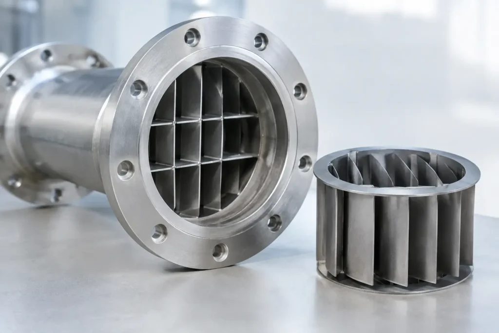
A vane flow straightener uses a set of longitudinal vanes arranged inside a pipe section. The vanes divide the flowing stream into smaller passages and suppress tangential velocity, or swirl. They also help redistribute velocity across the pipe bore after disturbances created by elbows, tees, reducers, pumps, valves, strainers, and partially open isolation valves.
The objective is a more stable, predictable velocity profile. Many meters do not measure total flow directly. They infer flow from velocity, pressure differential, vortex shedding, ultrasonic signal transit time, electromagnetic response, or another measured effect. When the incoming profile is distorted, the relationship between that measured effect and actual flow can shift.
A vane-style device is particularly effective where swirl is the main concern. Swirl is common downstream of two out-of-plane elbows, pump discharge piping, control valves, and certain compact skid layouts. The fluid may have the correct average flow rate, yet continue rotating through the line. That rotation can create meter bias, fluctuating signals, or poor repeatability.
Why Straight Pipe Is Not Always Enough
Straight-run requirements are often treated as a simple installation rule: provide a stated number of upstream and downstream pipe diameters, then install the meter. In real plants, that space is not always available. Existing pipe racks, valves, pump stations, skid boundaries, and structural constraints frequently force a tighter layout.
Even where sufficient straight pipe exists, its ability to correct a distorted profile depends on the severity of the disturbance, the fluid velocity, Reynolds number, and piping arrangement. A high-energy pump discharge followed by close-coupled elbows may need more recovery distance than the layout provides. A flow conditioner can reduce the required recovery length, but it does not make poor installation practices irrelevant.
Vane flow straighteners are therefore best viewed as an engineered response to a known hydraulic condition. They can make a compact installation perform more consistently, but they should be selected alongside the meter manufacturer’s installation guidance and the process requirements for accuracy.
Common Sources of Flow Distortion
The most frequent issues originate upstream. Centrifugal pumps can introduce swirl and nonuniform velocity, especially when discharge piping changes direction immediately. Elbows create secondary flows, and two elbows in different planes can generate a particularly persistent rotating profile. Control valves, reducers, partially obstructed strainers, and branch connections can also leave the flow uneven as it enters an instrument.
In chemical injection systems, the injection point itself may create a localized concentration and velocity disturbance. If a meter must verify carrier flow or totalized product flow downstream, pipe arrangement and injection-quill location both deserve review. Flow conditioning cannot correct an improperly dispersed chemical injection stream, but it can help establish a stable bulk-flow profile for measurement.
Selecting a Vane Flow Straightener
The first selection question is not the nominal pipe size. It is the function of the device in the system. Is the goal to reduce swirl before a magnetic flow meter? Improve repeatability at an ultrasonic meter? Stabilize flow before a control element? Support an OEM skid that must fit inside a defined footprint? Each application can point to a different geometry, length, material, and connection style.
Match the Geometry to the Disturbance
Vane configurations are designed primarily to remove rotational components from the stream. The number of vanes, their radial arrangement, vane thickness, and overall element length influence the degree of conditioning and pressure loss. More aggressive conditioning can improve profile control, but it may add differential pressure and create additional surfaces for fouling in dirty service.
For relatively clean water, solvents, hydrocarbons, and many process liquids, a compact vane assembly may be an effective choice. For slurries, fibrous fluids, polymer solutions, or services with solids that can bridge or accumulate, vane spacing requires careful attention. A device that performs well in clean water can become a maintenance point in a contaminated or viscous line.
Confirm Pressure Drop and Operating Range
Every internal flow-conditioning element creates some pressure loss. In many applications the loss is modest, but it still matters when available pump head is limited, when flow is gravity driven, or when the process operates near a control valve’s pressure-drop limit.
Pressure drop is not constant across operating conditions. It changes with fluid density, viscosity, velocity, and the device geometry. Specify minimum, normal, and maximum flow rates, along with temperature and pressure, rather than evaluating the component at one nominal condition. A unit that is acceptable at normal production flow may be restrictive during a high-rate flush or peak-demand cycle.
Select Materials for the Actual Process
Material selection should address chemical compatibility, temperature, pressure, cleaning procedure, and mechanical durability. Stainless steel is a common choice for industrial process service and sanitary applications, while PVC, CPVC, PVDF, PFA-lined construction, and specialty alloys may be appropriate for corrosive chemical duties.
The wetted vanes and housing should be considered together with gaskets, flanges, weld procedures, and adjacent piping materials. For sanitary service, cleanability and surface finish can be as significant as corrosion resistance. For aggressive acid, caustic, or oxidizing environments, a material that appears acceptable at ambient conditions may not be appropriate at elevated temperature or concentration.
Specify Connections and Installation Orientation
A flow straightener should fit the piping system without creating unnecessary transitions near the instrument. Flanged, threaded, sanitary clamp, grooved, and custom-end connections may be available depending on line size and service requirements. Avoid abrupt reducers or fittings immediately between the conditioner and meter unless the installation has been evaluated as a complete assembly.
Most vane devices are installed with attention to flow direction and alignment. If the unit includes a directional arrow, it is not optional. The assembly should also be accessible for inspection when the service is prone to deposits, solids, scale, or polymer buildup.
Flow Straightener vs. Flow Conditioner
The terms are sometimes used interchangeably, but they are not always identical. A vane flow straightener is principally intended to remove swirl and align the flow. A broader flow conditioner may also address velocity-profile distortion through perforated plates, tube bundles, structured elements, or proprietary geometries.
The appropriate option depends on what is causing the measurement problem. If a strong rotational component is present downstream of elbows or a pump, a vane device can be a direct and efficient solution. If the profile is severely asymmetric, or if a meter manufacturer calls for a specific conditioning performance, a different conditioner design may be more suitable.
This distinction matters when replacing equipment. Installing a generic straightener where a tested conditioner is required can produce a layout that looks correct but does not meet the intended meter-performance target.
Where Vane Devices Deliver Value
Vane-style conditioning is used across water and wastewater systems, chemical processing, oil and gas handling, power-generation auxiliaries, food and beverage transfer, pharmaceutical utilities, and OEM process skids. The common requirement is dependable flow behavior before sensitive equipment.
They are especially practical in retrofit work. A plant may be unable to relocate a meter or add several pipe diameters of straight run, yet still need more consistent readings for custody tracking, batching, chemical feed, or closed-loop control. An engineered flow-conditioning section can be installed within the available footprint while accounting for pressure, materials, connections, and meter location.
ProMixUSA supports these applications with flow-conditioning equipment and custom process solutions built around the actual piping and operating conditions. For critical measurement service, providing a piping sketch, fluid data, expected flow range, and downstream instrument details leads to a more reliable recommendation than selecting by pipe size alone.
A stable measurement begins upstream of the meter. When piping disturbances are treated as a process-design issue rather than a nuisance, vane flow straighteners can turn variable flow behavior into a controlled, repeatable operating condition.