
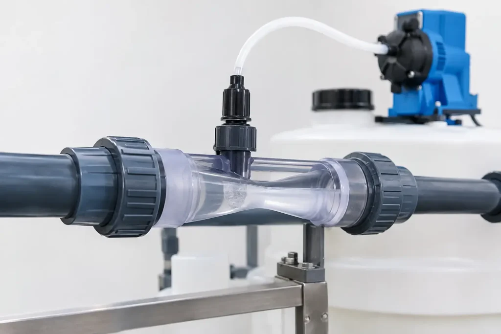
A chemical feed system can have an accurate metering pump and still deliver inconsistent treatment if the injection point cannot reliably pull in, disperse, or retain the chemical stream. Venturi injectors address that problem by using process-flow energy to create suction and introduce a secondary liquid, gas, or slurry stream without a motor, seal, or rotating component.
For industrial water treatment, chemical processing, wastewater, CIP systems, and other continuous-flow applications, that simplicity is valuable. But a venturi is not a universal substitute for a pump or an injection quill. Its performance depends on available pressure differential, flow stability, chemical compatibility, downstream backpressure, and the degree of mixing the process actually requires.
How venturi injectors create suction
A venturi injector uses a restricted flow path to convert pressure into velocity. As the motive fluid enters the converging section and reaches the throat, its velocity increases and static pressure drops. That lower pressure at the suction port draws in the secondary fluid. The combined stream then enters a diffuser section, where part of the pressure is recovered as velocity decreases.
This is a straightforward principle, but field results are governed by the full hydraulic system. The injector needs enough pressure at its inlet and low enough pressure at its outlet to maintain the required differential across the device. If downstream pressure rises, motive flow drops, or the suction source is placed under excessive vacuum lift, chemical draw can decline sharply or stop altogether.
The practical result is that venturi sizing starts with real operating pressures and flows, not just nominal pipe size. A unit that performs well at one flow condition may provide poor suction during turndown, intermittent operation, or a change in filter loading.
Where venturi injectors fit best
Venturi injectors are especially effective where a pressurized carrier stream is already available and a process benefits from a compact, low-maintenance method of introducing an additive. Common duties include drawing sodium hypochlorite, acids, caustics, coagulants, corrosion inhibitors, liquid nutrients, cleaning chemicals, and other treatment fluids into a water or process line.
They are also used for gas entrainment and aeration duties when the operating conditions, gas rate, and materials are selected appropriately. In these applications, bubble size, contact time, and downstream mixing must be considered. Creating suction is not the same as achieving complete dissolution or a uniform concentration at the point of use.
The absence of moving parts is a major operating advantage. There are no pump seals to leak, motors to maintain, or mechanical drives to align. For remote systems or corrosive services, this can reduce routine maintenance and simplify equipment layout.
That benefit comes with a trade-off. A venturi consumes pressure. If the process cannot spare the required pressure loss, a booster pump, recirculation loop, or another injection approach may be necessary. Systems with highly variable flow may also need a bypass arrangement, pressure regulation, or multiple injector sizes to maintain dependable draw across the operating range.
Specify the hydraulic conditions before the material
Material selection matters, particularly with aggressive chemicals, but hydraulics come first. The following operating information should be established before selecting a venturi injector:
- Motive-fluid flow rate, including minimum, normal, and maximum conditions
- Inlet pressure and expected outlet or downstream backpressure
- Required suction rate for the chemical or gas stream
- Suction lift, feed-tank level range, and length of the suction line
- Fluid temperature, viscosity, specific gravity, vapor pressure, and solids content
- Required injection concentration and downstream mixing distance
These values reveal whether the unit can generate sufficient vacuum at the intended chemical feed rate. They also expose problems that are often missed during initial design. For example, a chemical tote placed well below the injector creates additional suction lift. A long, undersized suction line introduces friction loss. A restrictive check valve, clogged strainer, or partially closed discharge valve changes the pressure balance the injector depends on.
For viscous chemicals, the concern is not only suction capacity but repeatability. A venturi calibrated around water-like viscosity may not pull a dense polymer, concentrated syrup, or cold viscous reagent at the same rate. In those cases, a positive-displacement feed pump may control dosage more accurately, while the venturi or a downstream static mixer supports dispersion.
Backpressure is often the deciding variable
A venturi injector needs a meaningful pressure difference between its inlet and outlet. The required differential varies by geometry and duty, but the principle does not: rising outlet pressure reduces available suction.
This is why location matters. Installing an injector upstream of a high-pressure membrane system, restrictive control valve, or long small-diameter pipe run can eliminate the pressure margin needed for chemical draw. A recirculation loop with a dedicated pump and controlled pressure drop is often a better arrangement when the main line cannot provide stable conditions.
Gauge pressure alone does not tell the full story. Engineers should evaluate pressure at the injector inlet and outlet under actual flow, including the effects of filters, piping losses, valves, and process equipment in their normal operating condition.
Chemical compatibility and construction options
Once hydraulic performance is established, select wetted materials for the chemical, temperature, concentration, and cleaning requirements. PVC and CPVC are widely used for many water-treatment chemicals. PVDF and PFA can be appropriate for more aggressive chemical service. Stainless steel, specialty alloys, and lined constructions may be required for elevated temperatures, solvents, sanitary duties, or difficult corrosive environments.
Compatibility should include more than the injector body. The suction connection, check valve, gaskets, O-rings, tubing, fittings, and any calibration equipment must also withstand the chemical. A chemically compatible venturi body does not prevent failure at an incompatible elastomer seal or a brittle suction tube.
For sodium hypochlorite and other off-gassing chemicals, consider vapor handling and suction-line design. Gas accumulation can interrupt chemical draw, create erratic feed rates, and make priming difficult. Short, properly sized suction runs and appropriate check-valve selection help limit those issues.
Injection quality requires more than entrainment
A venturi creates localized turbulence as the secondary stream enters the motive flow. That may be enough for applications where immediate rough blending is acceptable. It may not be enough for processes that demand a highly uniform concentration, controlled reaction time, or consistent sampling result.
When dispersion quality matters, pair the injection point with adequate straight-run length, turbulent process flow, or a downstream inline static mixer. Static mixing elements divide and recombine the flow repeatedly, improving chemical distribution without adding a rotating drive. The right arrangement depends on flow regime, viscosity ratio, chemical dose, pipe diameter, and the distance available before the next process step.
An injection quill can also be useful when the chemical must enter near the pipe centerline, away from the wall boundary layer, or in a direction that supports the main flow. In demanding applications, the strongest design is often a system rather than a single component: controlled chemical feed, a properly sized venturi or quill, and downstream static mixing engineered for the required uniformity.
Installation and operating details that protect performance
Venturi injectors should be installed with accessible pressure gauges or transmitters at the inlet and outlet during commissioning. Those readings allow operators to verify that the expected differential exists and diagnose a loss of suction before treatment performance is affected.
Keep the suction line as short and direct as practical. Avoid unnecessary high points where vapor can collect, and use a foot valve or injection check valve where the application requires it. The suction-side components must have low enough cracking pressure and flow resistance to avoid consuming the available vacuum.
Plan for flushing. Chemical crystallization, scaling, solids, and precipitates can obstruct the throat or check valve, particularly when incompatible chemicals meet or when a feed line sits idle. A clean-water flush connection can reduce downtime and make maintenance safer.
ProMixUSA supports venturi equipment alongside injection quills, calibration columns, static mixers, and complete chemical-injection systems, allowing the injection method and mixing requirement to be evaluated together rather than as separate purchases.
The best venturi installation is not the one with the lowest component count. It is the one that maintains sufficient pressure differential, delivers the required feed rate under real operating conditions, and provides the downstream mixing needed to protect process quality.