
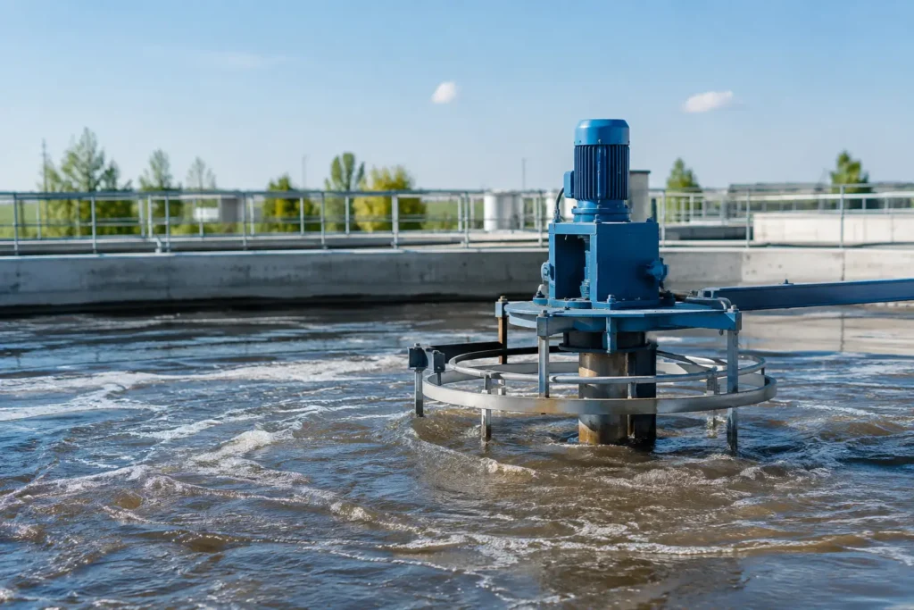
A wastewater mixing example is most useful when it follows the chemical from the injection point to the treatment result. Consider a municipal or industrial plant dosing ferric chloride ahead of clarification to remove phosphorus and improve solids capture. The chemical pump may be accurate, but if the ferric stream enters a large pipe and remains concentrated along one side, the process can produce uneven floc, excess chemical use, and variable effluent quality.
The solution is not automatically a larger mixer. It is an engineered mixing arrangement that accounts for flow rate, pipe size, fluid properties, chemical dose, available pressure drop, residence time, and the downstream process. That is where equipment selection becomes a process decision rather than a catalog decision.
Wastewater Mixing Example: Ferric Chloride Dosing
Assume a treatment plant processes 2.0 million gallons per day through a 12-inch force main before a flocculation basin. Its normal flow is approximately 1,390 gallons per minute, with lower nighttime flows and higher wet-weather peaks. The plant injects a 40% ferric chloride solution to precipitate phosphorus and support coagulation.
At the normal flow condition, the main carries wastewater at roughly 4 feet per second. A small chemical injection line discharges ferric chloride into the main at 8 gallons per hour. The dose volume is tiny compared with the carrier flow, but its effect is substantial. The injected chemical must spread across the full pipe cross-section quickly enough to react consistently before the water reaches the flocculation basin.
A simple injection tee may create some local turbulence, especially at high flow. It does not guarantee uniform concentration across the pipe, however. At low flow, the ferric stream can travel as a concentrated plume. At higher flow, the plume may shift with velocity profile changes, pipe bends, valves, and pump cycling. Operators may respond by increasing dose, only to create excess sludge, lower alkalinity, or downstream pH-control problems.
In this application, a fixed injection quill places the ferric discharge at a controlled location in the pipe, commonly near the centerline or in the region of greatest velocity. A static mixer installed downstream then divides and redirects the combined flow through successive mixing elements. Each element creates additional interfaces between the chemical and wastewater. The result is a more uniform chemical distribution without motors, shafts, seals, or electrical controls.
Selecting the Mixing Equipment
The first question is not whether a static mixer can mix ferric chloride. It can. The real question is whether the mixer geometry can deliver the required blend quality within the plant's pressure-drop allowance.
For this example, an inline static mixer may be specified in a 12-inch diameter with a defined number of elements. The mixer length and element count depend on the desired coefficient of variation, the Reynolds number, chemical viscosity, and the distance available before the flocculation basin. Municipal wastewater is often relatively low in viscosity, but solids concentration, temperature, and hydraulic variation still matter.
A static mixer is a strong fit when flow is continuous, the pipe remains full, and the available differential pressure can support the mixing elements. It is compact, reliable, and well suited to chemical dosing applications where repeatability matters every shift. It also eliminates mechanical drive maintenance in a corrosive environment.
There are trade-offs. More elements generally improve distribution, but they also increase pressure drop. A mixer selected only for the average flow may underperform during low-flow operation. Conversely, a unit sized for high peak flow can impose unnecessary head loss during normal service. A sound design evaluates the full operating envelope, including minimum, normal, and maximum flow.
If the process needs high-energy dispersion, such as breaking apart oily emulsions, dispersing polymers, or rapidly hydrating dry chemicals, a static mixer alone may not be enough. A high-shear mixer, tank mixer, or complete chemical make-down system may be the better answer. The equipment must match the mixing mechanism required by the chemistry.
Injection Location Matters as Much as Mixer Length
The injection point should be located upstream of the static mixer with enough straight pipe to avoid direct impingement on an element. The quill design must also prevent the chemical from collecting along the pipe wall or flowing backward into the injection line.
For ferric chloride, wetted material selection is critical. Depending on concentration, temperature, and plant standards, PVC, CPVC, PVDF, alloy materials, or lined components may be considered. The quill, isolation valve, check valve, tubing, and mixer body should be reviewed as one chemical-contact system. A corrosion-resistant static mixer body does not solve a problem created by an incompatible injection assembly.
The same approach applies to sodium hypochlorite, sulfuric acid, caustic, polymer, lime slurry, and odor-control chemicals. Each chemical introduces its own compatibility, deposition, gas-release, and safety considerations.
Verifying the Result in the Field
The plant should not assume that installing a mixer guarantees a process improvement. Field verification establishes whether the equipment is doing its job under real hydraulic conditions.
A practical test begins by measuring the residual or tracer concentration at multiple points downstream of the mixer. For a ferric application, the team may compare soluble phosphorus removal, settled-water turbidity, sludge production, and chemical consumption before and after installation. The objective is not always a perfectly uniform number at every sample point. It is stable enough distribution to achieve the treatment target without overfeeding chemical.
Pressure gauges installed upstream and downstream of the mixer are equally valuable. They confirm actual differential pressure and help identify fouling, blockage, or unexpected hydraulic changes. In wastewater service, ragging and solids accumulation should be considered during design, particularly where upstream screening performance is inconsistent.
A well-designed system also considers access. If a static mixer is installed in a location that cannot be isolated, inspected, or replaced without a prolonged outage, maintenance risk has simply moved downstream. Flanged connections, spool-piece arrangements, removable elements, and appropriate valve placement can make a major difference over the equipment life cycle.
When a Tank Mixer Is the Better Wastewater Mixing Example
Now consider a different part of the same plant: a 15,000-gallon equalization tank receiving variable industrial wastewater. Flow and pH change throughout the day, and chemicals are added to neutralize acidic batches before biological treatment. Here, inline mixing in the discharge pipe cannot correct concentration gradients that already exist inside the tank.
A top-entry or side-entry mechanical mixer is the appropriate tool because the objective is bulk tank turnover. The selected impeller must suspend solids where needed, prevent stratification, and create enough circulation to distribute the neutralizing chemical throughout the vessel. The design should account for liquid level range, tank geometry, baffles, solids loading, and the required blend time.
This application illustrates a common specification mistake: treating all mixing as a single problem. Inline static mixers excel at continuous pipe-flow blending. Mechanical tank mixers create circulation in a vessel. High-shear equipment reduces droplet or particle size. Injection quills place chemicals safely and predictably. A complete wastewater system may use all four.
Design Inputs That Prevent Expensive Rework
Before specifying equipment, collect the operating information that defines the duty. At minimum, the engineering review should include:
- Minimum, normal, and maximum liquid flow rates
- Pipe or tank dimensions, orientation, and available installation space
- Wastewater composition, solids content, temperature, density, and viscosity
- Chemical identity, concentration, feed rate, and required materials compatibility
- Available pressure drop for inline equipment or power limits for mechanical mixers
- Required mixing quality, reaction time, and downstream treatment objectives
These inputs allow the equipment supplier to model a realistic solution instead of sizing from nominal pipe diameter alone. Computational flow analysis can be especially useful where a chemical injection point sits near elbows, reducers, flow meters, valves, or multiple feed lines. Those features change the velocity profile and can affect distribution quality.
For demanding chemical-feed systems, ProMixUSA can engineer static mixers, injection quills, and complete skid-mounted assemblies around the actual piping, material, and operating conditions. That approach helps plants avoid field modifications that delay startup or compromise safe chemical injection.
The Practical Lesson
The value of this wastewater mixing example is not that ferric chloride always requires the same mixer. A plant with a short run of pipe, highly variable flow, limited pumping head, or multiple chemical feeds may require a different geometry, injection method, or tank-based mixing strategy.
Start with the treatment objective, then follow the fluid path. When chemical placement, mixing energy, materials selection, and verification are engineered together, operators gain more stable results without using excess chemistry to compensate for poor distribution.