
A gas stream can look fully dispersed at a sampling point and still create poor mass transfer, unstable downstream pressure, or unacceptable carryover farther down the line. That is why a gas liquid mixing guide must begin with the process duty, not simply the mixer body size. The right solution depends on whether the objective is gas dissolution, chemical reaction, oxidation, stripping, flotation, aeration, foam control, or controlled two-phase delivery to downstream equipment.
For industrial systems, gas-liquid mixing is a balance of bubble size, residence time, pressure drop, liquid velocity, gas-to-liquid ratio, and equipment geometry. A design that produces excellent dispersion can also consume excessive pressure. A low-pressure design may preserve pump capacity but leave large bubbles and uneven concentration profiles. Engineers need to establish the operating window before selecting a static mixer, injection quill, venturi, sparger, or mechanically agitated vessel.
What Gas-Liquid Mixing Must Accomplish
Gas-liquid mixing is not a single performance target. In some applications, the process needs the gas to dissolve rapidly into the liquid. In others, the goal is a consistent dispersed phase that remains intact until it reaches a reactor, contact tank, separation step, or spray device. These are different duties and they require different equipment decisions.
Ozone injection into water, for example, requires fine dispersion and sufficient contact time while accounting for material compatibility and gas safety. Carbon dioxide addition may require controlled dissolution without excessive pH swings or vapor lock. Air or oxygen injection for oxidation often demands repeatable gas distribution across changing flow rates. Chlorine, hydrogen, hydrogen sulfide, and other hazardous gases require an added level of containment, injection control, and materials review.
The liquid itself drives much of the design. Clean, low-viscosity water behaves very differently from a shear-sensitive polymer solution, a viscous slurry, or a liquid carrying suspended solids. Gas dispersion becomes more difficult as viscosity increases, while solids can foul small injection ports and narrow mixer passages. The correct system is the one that maintains performance in the real process fluid, not only in ideal water testing.
Define the Process Window Before Selecting Equipment
A useful gas liquid mixing guide starts by documenting normal, minimum, and maximum operating conditions. Design around a single flow rate and the equipment may fail when the plant turns down production or operates during startup.
At minimum, establish liquid flow rate, gas flow rate, line pressure, temperature, liquid viscosity, density, solids content, available differential pressure, and allowable pressure drop. Also identify the required outlet condition. Is the gas expected to dissolve? Is a specific dissolved-gas concentration required? Must bubbles remain below a defined size? Is the outlet feeding a tank, membrane, filter, reactor, or meter that can be affected by entrained gas?
Gas flow should be expressed at clearly defined conditions. Standard cubic feet per minute and actual cubic feet per minute are not interchangeable. As line pressure changes, the actual gas volume in the pipe changes substantially. This affects gas velocity, void fraction, mixer loading, and the risk of flow regime changes.
The gas-to-liquid ratio matters, but it is not enough on its own. A moderate gas ratio at high pressure can be manageable, while the same standard gas flow at low pressure may create large gas pockets and slugging. The design team should also consider whether gas supply pressure remains reliably above process pressure, including transient conditions.
Select the Mixing Method for the Duty
Inline static mixers are often the most efficient choice when continuous liquid flow is available and the process can tolerate a controlled pressure drop. Fixed internal elements divide and redirect the liquid stream repeatedly, creating interfacial area between gas and liquid without moving parts. For pipeline injection, this provides repeatable mixing with low maintenance and no motor or seal system.
Static mixing works especially well when the gas is introduced upstream through a properly designed injection point and the line velocity is sufficient to carry the phases through the mixer. Element geometry, diameter, length, and mixer material must be matched to the flow regime and chemical service. More elements generally improve distributive mixing, but they also increase pressure loss. There is no value in specifying maximum mixing intensity if the resulting pressure drop causes pump instability or constrains plant throughput.
Venturi equipment can be effective where the process has adequate liquid-side pressure available. The venturi creates a low-pressure zone that can draw in gas or improve gas entrainment. It may be a practical option for recirculation systems, water treatment, and chemical injection loops. Its limitations are equally important: performance is tied closely to liquid flow and available differential pressure, so significant turndown can reduce gas induction and dispersion quality.
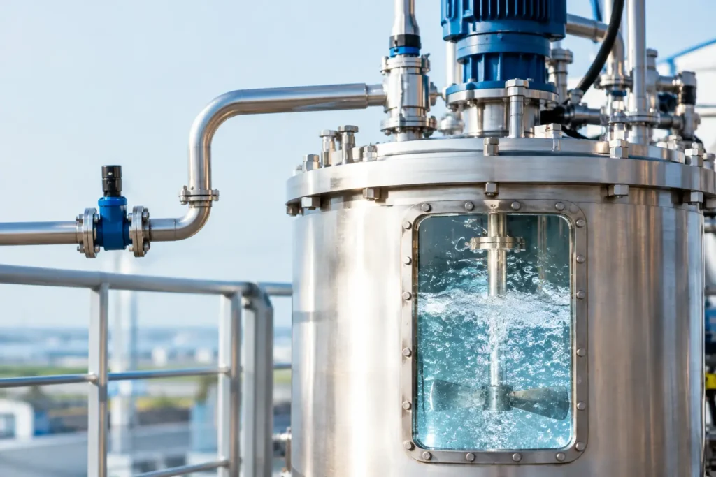
For vessels, side-entry, top-entry, or high-shear mechanical mixers may be required when the process needs longer contact time, batch control, or dispersion through a large liquid volume. Tank agitation can prevent stratification and provide residence time that an inline system cannot. However, mechanical mixing adds maintenance requirements, shaft sealing considerations, installation constraints, and energy use. In hazardous gas service, seal selection and vapor containment deserve the same attention as impeller selection.
Injection Location Controls the Result
A high-performance mixer cannot correct every poor injection arrangement. Gas introduced through an oversized open pipe can form a large pocket before it reaches the mixing zone. Once slug flow develops, downstream static elements may see alternating gas and liquid rather than a stable two-phase stream.
An injection quill provides controlled entry into the flowing liquid and positions the gas where local turbulence and liquid velocity can act on it immediately. Quill depth, tip orientation, nozzle size, and material selection should be designed around the pipeline velocity and chemical behavior. For reactive or corrosive gas service, retractable injection designs can also simplify inspection and maintenance while supporting safe isolation practices.
Place the injection point far enough upstream to allow the mixer to process the two-phase stream, but avoid unnecessary straight pipe that lets gas coalesce before entering the mixing elements. Downstream piping also matters. Vertical flow direction, elevations, elbows, pressure-control valves, and dead legs can all change bubble behavior after the mixer.
Manage Pressure Drop, Flow Regime, and Bubble Size
The most common design error is treating pressure drop as an afterthought. Static mixing performance comes from using hydraulic energy already present in the system. The mixer converts some of that energy into turbulence, flow division, and interfacial renewal. If the system does not have sufficient available pressure, the equipment cannot deliver the intended result.
At very low liquid velocities, gas may stratify at the top of a horizontal line. At higher velocities, the flow may transition through intermittent, slug, annular, or dispersed regimes. These transitions are not merely academic. They affect pressure stability, gas hold-up, meter accuracy, and the amount of mixing required.
Bubble size influences mass transfer because smaller bubbles provide more surface area per unit of gas volume. Yet extremely aggressive shear is not always desirable. It can cause foaming, damage shear-sensitive formulations, increase pressure drop, or complicate downstream gas separation. The target should be the bubble distribution that serves the process objective, not the smallest possible bubble.
Materials and Safety Are Part of Mixer Selection
Gas-liquid systems often combine chemical exposure, pressure, and off-gassing risk. Select wetted materials for the complete chemistry, including dissolved gas, condensate, cleaning chemicals, temperature, and concentration excursions. Stainless steel may be appropriate for many services, but chlorides, strong acids, oxidizers, and specialty gases may call for PVDF, PFA, CPVC, lined construction, or specialty alloys.
Connection type and pressure rating must match the actual installation. Flanged, threaded, sanitary, tri-clamp, or custom connections each introduce different maintenance and containment considerations. Where the gas is toxic, flammable, or oxidizing, the package should also account for isolation valves, check valves, pressure relief, leak detection, ventilation, and operating procedures.
A safe chemical injection system should prevent liquid backflow into the gas supply and limit the consequences of a pressure upset. Check valves are necessary in many systems, but they are not a substitute for engineering the supply pressure, shutoff sequence, and maintenance isolation plan.
Validate Performance Under Real Conditions
Factory calculations and mixer simulation provide a strong starting point, but commissioning should verify the actual process result. Measure differential pressure across the mixer, liquid and gas flow, inlet and outlet pressure, and the variable that matters most to the operation: dissolved oxygen, pH, oxidation-reduction potential, reaction conversion, concentration uniformity, or another defined quality metric.
Testing should include more than the nameplate condition. Confirm performance at expected turndown, during startup, and at realistic liquid temperatures. If the system produces vibration, pulsation, excess foam, or unstable pressure, investigate the injection location and flow regime before increasing mixer length. More mixing elements may help, but they may also treat the symptom rather than the cause.
ProMixUSA engineers static mixing, injection, and flow-conditioning equipment around actual piping, chemistry, and operating requirements. That application-first approach helps avoid common failures such as inadequate pressure margin, incorrect materials, oversized injection ports, and equipment that performs only at one flow rate.
The best gas-liquid system is rarely the most aggressive mixer on the specification sheet. It is the system that delivers a repeatable outlet condition, protects people and equipment, and continues to perform when flow, pressure, and production schedules change.