
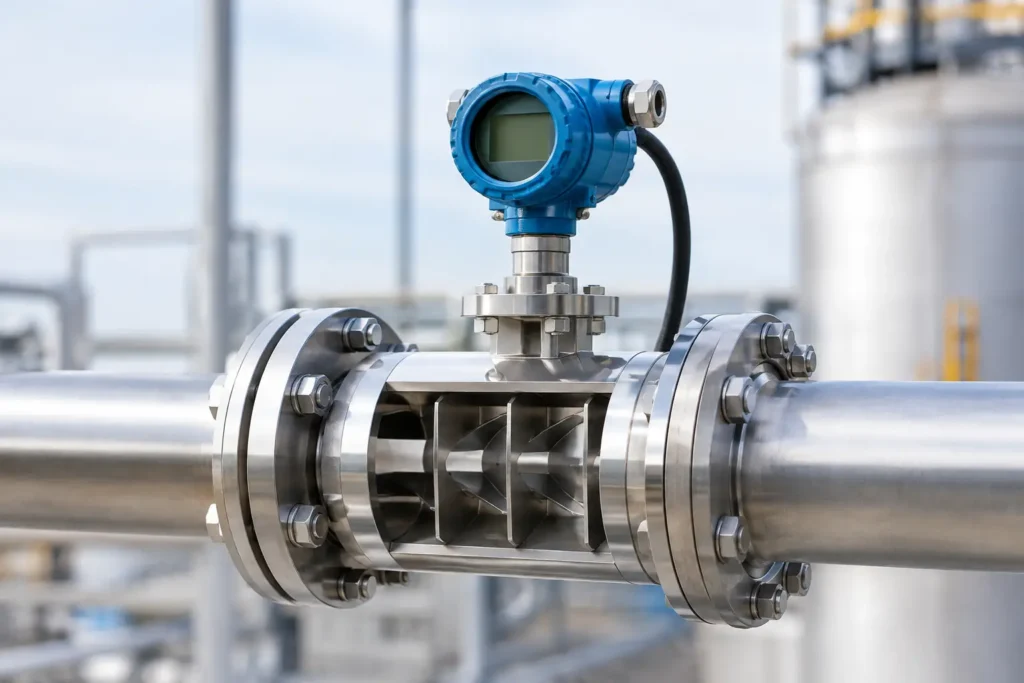
A flowmeter can be correctly sized, calibrated, and installed in the correct line size, then still deliver unreliable data because the fluid entering it is rotating, asymmetric, or unstable. Flow conditioners address that upstream problem. Installed ahead of sensitive instruments or process equipment, they reorganize the velocity profile so downstream devices receive flow conditions closer to those assumed in their design and calibration.
For plants managing chemical injection, batching, custody transfer, treatment processes, or quality-critical production, this is not a minor piping detail. Poor approach flow can create unexplained measurement drift, repeatability problems, alarm noise, and unnecessary troubleshooting. The right conditioner can reduce those risks without requiring major changes to the process layout.
What Flow Conditioners Do in a Piping System
A flow conditioner is an inline device designed to reduce swirl and redistribute velocity across a pipe cross-section. It does not mix chemicals or intentionally create shear like a static mixer. Its role is to prepare the flow for a meter, analyzer, control valve, pump, or other component that performs best with a stable approach profile.
Flow leaving an elbow, tee, reducer, partially open valve, pump discharge, or poorly arranged manifold is rarely ideal. A single elbow can introduce uneven velocity. Two elbows in different planes can add significant swirl. Pump discharge piping may deliver pulsation, recirculation effects, or rotating flow that persists far downstream. In tight equipment rooms and packaged skids, there may not be enough straight pipe to allow these disturbances to decay naturally.
A properly engineered flow conditioner uses internal geometry to break up large-scale rotation and distribute the stream more evenly. Depending on the design, that geometry may include perforated plates, tube bundles, vanes, or proprietary conditioning elements. The goal is not to create a perfectly uniform profile under every operating condition. The goal is to reduce the distortions that materially affect downstream performance.
Why Meter Accuracy Depends on Upstream Flow
Many flow technologies are sensitive to the way fluid enters the meter body. Differential-pressure devices, turbine meters, vortex meters, ultrasonic meters, and electromagnetic meters can all be affected by installation conditions, although the nature and severity of the effect vary by meter type and manufacturer.
A distorted velocity profile can bias a measurement because the meter interprets fluid behavior through a limited sensing area or a specific measurement principle. Swirl may cause a turbine rotor to respond differently than expected. An ultrasonic meter can see altered signal paths. A differential-pressure device can experience a pressure distribution that does not match its assumed coefficient. Even when the average flow rate is unchanged, the meter output may shift.
This is why straight-run requirements are usually stated in pipe diameters upstream and downstream of an instrument. Those recommendations are useful, but they are not interchangeable with a conditioning strategy. Ten diameters of straight pipe after a major disturbance may be sufficient in one service and inadequate in another. Reynolds number, viscosity, pipe roughness, fitting geometry, flow range, and the required measurement uncertainty all matter.
When space is limited, a flow conditioner can reduce the straight-run distance required to achieve acceptable performance. It should not be treated as a universal shortcut. The installation still needs to follow the meter supplier's approved configuration, particularly where a meter is used for regulated reporting, custody transfer, or a process control loop with tight tolerances.
Where Flow Conditioners Deliver the Most Value
The strongest use case is a line where measurement quality matters but piping geometry is constrained. Skid-mounted chemical injection systems are a common example. The available footprint may place a meter shortly after a pump, isolation valve, check valve, or elbow. Without conditioning, the meter may be operating in a disturbed profile every time the skid runs.
They are also valuable in transfer lines, water and wastewater treatment systems, blending operations, food and beverage processing, pharmaceutical utility systems, and oil and gas service. In each case, the objective is similar: stabilize the approach flow before a critical measurement or process step.
Consider a flow conditioner when a new meter produces unstable readings despite proper electrical setup and calibration; when a piping modification changes previously dependable meter performance; when straight-run requirements cannot be met; or when a meter manufacturer identifies swirl as a likely source of error. It can also be specified proactively when designing a compact skid around a known measurement requirement.
Not every application needs one. A long, straight pipe run with no significant upstream disturbance may already provide suitable conditions. Adding a conditioner where it provides no measurable benefit creates extra pressure drop, added cost, and another component to inspect. Selection should be driven by the process, not by a generic rule.
Selecting Flow Conditioners for the Application
The first step is to define the downstream equipment and the performance target. A meter used for general trend monitoring has different needs than one controlling chemical dosage or documenting transferred volume. Start with the required flow range, allowable pressure loss, line size, fluid properties, operating temperature and pressure, and upstream piping arrangement.
Material selection follows the actual service conditions. Stainless steel is a practical choice for many industrial and sanitary applications, but it is not automatically correct for chlorides, aggressive acids, caustics, or high-purity chemicals. PVC, CPVC, PVDF, PFA-lined construction, specialty alloys, and other materials may be better suited to corrosive service. The body, internal elements, welds, gaskets, and connections all need compatible materials.
Connection details matter as much as nominal pipe size. Flanged, threaded, tri-clamp, socket weld, and custom end connections affect installation, cleanability, pressure rating, and maintenance access. For sanitary systems, internal finish and clean-in-place requirements may guide the design. For hazardous chemical service, containment, flange ratings, and gasket selection deserve equal attention.
Pressure drop is the central trade-off. More aggressive internal geometry may offer stronger conditioning, but it also consumes available head. On a gravity line, low-pressure utility system, or pump operating near its limit, that loss can be unacceptable. Conversely, a low-loss device may not provide enough correction for severe swirl in a compact layout. The best selection balances conditioning performance with hydraulic capacity rather than maximizing either one in isolation.
Installation Details That Affect Results
A flow conditioner must be installed in the intended orientation and location. Placing it too close to a source of severe disturbance can reduce its effectiveness, while placing an additional elbow, valve, or reducer between the conditioner and meter can reintroduce the problem it was meant to solve.
The entire piping sequence should be reviewed: pump discharge, fittings, valves, injection points, conditioner, meter, and downstream restrictions. Chemical injection upstream of a meter may introduce density gradients or incomplete blending that no flow conditioner is designed to correct. In that case, the system may need an injection quill and static mixer to achieve homogeneous concentration before measurement.
Keep internal surfaces clean. Scale, polymer buildup, debris, and damaged elements can alter pressure loss and flow distribution over time. Where solids or fouling are expected, specify a configuration that can be inspected and serviced, and include maintenance access in the layout. A conditioned flow profile is only repeatable when the device remains in its intended internal condition.
Flow Conditioning Is Not Static Mixing
The terms are occasionally confused because both products install inline and contain internal elements. Their functions are different. A static mixer creates controlled division and recombination of flowing streams to blend additives, disperse phases, transfer heat, or drive a reaction. It deliberately produces mixing energy from the line flow.
A flow conditioner is designed primarily to reduce swirl and profile distortion ahead of equipment. Some conditioning devices may create limited redistribution that looks like mixing, but they should not be selected as a substitute for a properly sized static mixer when concentration uniformity is required.
That distinction is especially relevant in chemical treatment systems. If a process requires safe chemical injection, uniform reagent distribution, and accurate downstream flow measurement, the engineered solution may include both technologies. The injection point, quill design, static mixer, conditioning section, and meter location should be considered as one system.
Specify the Device Around the Whole Process
A reliable specification begins with an accurate piping and instrumentation diagram, not just a pipe diameter. Provide the upstream and downstream layout, meter model, flow range, fluid chemistry, temperature, pressure, allowable pressure drop, material requirements, and any sanitary or regulatory constraints. If the application has a required uncertainty target, state it directly.
ProMixUSA supports these decisions with application-specific flow-conditioning equipment and broader system expertise in static mixing, chemical injection, and custom process skids. That broader view helps prevent a common mistake: correcting one component while leaving the upstream cause of instability untouched.
The most effective flow conditioner is the one that fits the actual hydraulic and measurement problem, not the one with the most complex internals. Review the full line arrangement before fabrication, reserve enough pressure drop for the device, and confirm the meter supplier's installation criteria. That work at the specification stage can prevent years of questionable process data.