
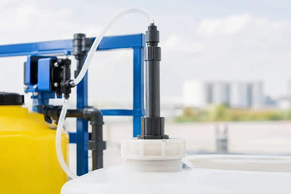
A chemical feed point can determine whether a treatment program performs as designed or creates a recurring maintenance problem. Fixed injection quills place the dosing outlet at a controlled position inside a process pipe, helping plants introduce chemicals away from the wall, into the intended flow zone, and with less exposure to backflow, corrosion, or poor dispersion.
For continuous, stable-duty applications, a fixed quill is often the most direct answer. It has no moving retrieval mechanism, fewer components to inspect, and a rigid installation that holds the injection point in a repeatable location. The right design, however, depends on much more than line size. Chemical reactivity, process pressure, fluid velocity, insertion depth, nozzle geometry, pipe orientation, and downstream mixing all affect results.
What Fixed Injection Quills Do
A fixed injection quill is a stationary assembly installed through a pipe connection, typically a threaded, flanged, socket-weld, or sanitary connection. Its wetted tube extends from the pipe wall toward the flowing process stream. Chemical enters through the quill and exits through a defined discharge point, commonly near the centerline or in a high-velocity region of the main flow.
This arrangement solves a common problem with wall-mounted injection ports. When concentrated chemical discharges directly against or near the pipe wall, it can create a localized high-concentration zone. With aggressive acids, caustics, oxidizers, biocides, or corrosion inhibitors, that zone may damage piping, promote deposits, or produce inconsistent treatment. Moving the outlet into the flowing stream reduces wall contact and gives the chemical a better starting point for distribution.
Fixed quills are used in water and wastewater treatment, power and utility systems, chemical processing, oil and gas facilities, pulp and paper operations, food and beverage systems, and OEM skids. Typical services include pH control, chlorine and hypochlorite dosing, coagulant addition, anti-scalant injection, polymer feed, corrosion inhibitor dosing, and catalyst or additive introduction.
Why Outlet Location Matters
The process line does not instantly mix an injected chemical. A quill improves the starting conditions, but it does not replace sound mixing design. The outlet should be located where the process stream can capture and carry the injected fluid rather than allowing it to hug the pipe wall or travel as a concentrated ribbon.
In turbulent liquid flow, a centerline or near-centerline discharge frequently provides strong exposure to the core stream. In other applications, injecting into a velocity gradient or directing the outlet downstream can be more effective. The best location depends on flow profile, line geometry, injection rate, chemical viscosity, and how much straight run is available before the next control point, instrument, heat exchanger, or vessel.
Injection direction also matters. A discharge pointing downstream generally minimizes the force opposing the process flow. In services where rapid dispersion is critical, an engineered outlet arrangement combined with an inline static mixer may be the better solution. Static mixing elements divide and recombine the flow repeatedly, providing predictable blending where pipe length alone is not enough.
Centerline Is Not Always the Correct Answer
Centerline placement is a proven default for many applications, but it is not universal. A large-diameter pipe with low flow velocity may need a different strategy than a small high-velocity line. A quill inserted too deeply can become vulnerable to vibration, erosion, or mechanical damage. One that ends too close to the wall may not prevent chemical attack at the pipe surface.
The goal is controlled exposure to the process stream, not a one-size-fits-all insertion depth. Engineering review should consider pipe inside diameter, schedule, expected flow range, pressure drop, chemical feed pressure, and any downstream equipment that needs a fully blended stream.
Selecting Materials for the Chemical and the Process
Material selection is central to fixed injection quill performance. The quill must withstand not only the injected chemical, but also the process fluid, temperature, pressure, cleaning chemicals, and possible upset conditions. A material that tolerates diluted chemical during normal operation may fail when a dosing pump delivers a concentrated slug during startup or calibration.
Stainless steel is widely used where corrosion resistance and mechanical strength are required. For more aggressive chemical environments, higher-alloy materials may be appropriate. PVC, CPVC, PVDF, PFA-lined constructions, and other engineered polymers can provide excellent compatibility in selected acid, caustic, and oxidizing services. Sanitary applications may require polished stainless construction, hygienic connections, and geometry that supports cleaning requirements.
The check valve deserves the same attention as the quill body. Its seat, spring, seals, and wetted internals must match the chemical service. A poorly selected valve can stick, leak, or allow process fluid to enter the chemical line. In many systems, the injection point should include isolation and backpressure control appropriate to the pump and process conditions.
Fixed Versus Retractable Injection Quills
The fixed configuration is best suited to processes that can be isolated or shut down when service is required, and where the quill does not face frequent plugging, scaling, or inspection needs. It is mechanically straightforward, economical, and dependable for continuous chemical dosing.
A retractable injection quill is designed for services where operators need to remove or inspect the assembly while the line remains pressurized. That capability can reduce downtime, particularly in high-value continuous processes. It also adds mechanical complexity, operating procedures, and maintenance requirements. Retractable equipment should be selected when live removal provides a clear operational advantage, not simply because it offers more features.
For a stable water-treatment loop or a process skid with planned shutdown windows, fixed equipment is often the practical choice. For a critical main line where taking the pipe offline is unacceptable, retractable designs may justify their added cost.
Installation Details That Affect Reliability
A fixed quill can be well built and still underperform if the installation ignores basic piping realities. The connection should be positioned where personnel can safely access isolation valves, tubing, and fittings. It should also avoid locations with severe vibration, dead legs, air accumulation, or inadequate downstream residence time.
Vertical and horizontal lines present different considerations. In a horizontal pipe, the injection point should be selected with awareness of phase separation, sediment, and whether gas can collect near the connection. In a vertical line, flow direction influences how the injected chemical enters and travels with the process stream. The chemical supply line should be properly supported so its weight does not load the quill or pipe connection.
Pressure differential is another frequent issue. The dosing pump must overcome process pressure, fitting losses, check-valve cracking pressure, and the quill discharge condition. If the pump cannot maintain adequate pressure, chemical delivery may become erratic. If pulsation is significant, a pulsation dampener, calibration column, backpressure valve, or injection assembly designed for the pump’s operating profile may be required.
When a Quill Needs a Static Mixer
A quill controls where the chemical enters. A static mixer controls how reliably it blends. The distinction is critical where treatment performance is measured only seconds downstream, where chemical demand changes quickly, or where the injected fluid has a substantially different viscosity or density than the carrier stream.
A static mixer is particularly valuable when a plant needs uniform concentration before a pH probe, conductivity meter, analyzer, membrane system, reaction zone, or distribution header. It can also reduce the straight-pipe length otherwise needed for acceptable mixing. The trade-off is pressure drop, so the mixer diameter, element geometry, and number of elements must be selected for the actual flow range and allowable system loss.
ProMixUSA engineers fixed injection quills alongside static mixers, calibration equipment, and complete injection skids when the process requires more than a simple pipe penetration. This approach helps align the injection point, materials, connections, and downstream mixing duty instead of treating them as unrelated purchases.
Common Causes of Poor Injection Performance
Many recurring injection problems originate from a few specification gaps. A quill may be too short for the pipe, use incompatible wetted materials, discharge into a low-velocity zone, or lack a reliable check valve. In other cases, the injection point is correct but the process lacks sufficient downstream mixing before measurement or reaction.
Plugging can occur when the injected chemical crystallizes, polymerizes, reacts with the process fluid, or sees a temperature change at the quill tip. Erosion can develop when abrasive process solids strike an improperly positioned tube. Vibration can fatigue long insertion lengths in high-velocity lines. These conditions call for application-specific geometry and material choices, not a generic quill selected only by nominal pipe size.
A complete specification should identify the process fluid, injected chemical concentration, temperature range, operating and design pressure, flow range, pipe size and schedule, connection type, required insertion length, and preferred material. It should also state whether the plant needs a check valve, isolation valve, flushing connection, calibration capability, or guaranteed downstream mixing performance.
The best fixed injection quill is the one that makes chemical addition predictable without becoming the next maintenance bottleneck. Start with the chemical and the line conditions, then engineer the outlet position and downstream mixing around the actual process duty.