
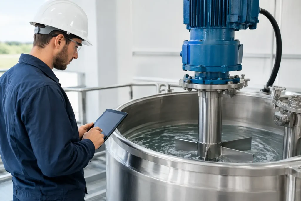
A tank mixer that looks adequately sized on a layout can still fail in service if its motor cannot overcome viscosity, startup load, gas dispersion demands, or changing batch conditions. Knowing how to calculate mixer power gives engineers a defensible starting point for selecting an impeller, gearbox, shaft, seal, and motor package that will perform under real plant conditions.
For a mechanically driven tank mixer, power is not determined by vessel volume alone. Tank geometry, fluid density, viscosity, impeller diameter, rotational speed, baffles, and the required mixing duty all affect the result. A 5,000-gallon blending tank handling water-like liquid may require far less power than a smaller vessel processing a shear-sensitive polymer solution.
How to Calculate Mixer Power From the Core Equation
The standard starting point for turbulent-flow agitator sizing is the impeller power equation:
P = Np × ρ × N³ × D⁵
Where:
- P is power at the impeller, in watts
- Np is the dimensionless power number for the impeller
- ρ is fluid density, in kilograms per cubic meter
- N is impeller rotational speed, in revolutions per second
- D is impeller diameter, in meters
This equation makes one design reality clear: impeller diameter has an outsized effect on power. Because diameter is raised to the fifth power, a moderate increase in impeller size can require substantially more motor power. Speed is also influential because it is raised to the third power.
For US customary calculations, many teams convert the result after completing the calculation in consistent SI units. Divide watts by 746 to estimate horsepower. It is usually more reliable to perform the engineering calculation in SI units, then convert the final shaft-power requirement to horsepower for motor selection.
The equation provides impeller power, not the final nameplate motor size. Motor and drivetrain selection must account for gearbox efficiency, service factor, process variability, startup torque, and any additional mechanical losses.
Determine the Flow Regime Before Selecting a Power Number
The power number is not a universal constant. It varies by impeller type and, in transitional or laminar flow, by Reynolds number. Before assigning an Np value, calculate the mixer Reynolds number:
Re = ρ × N × D² / μ
Where μ is dynamic viscosity in pascal-seconds, also expressed as kg/m·s.
In a turbulent regime, the power number for a given impeller and tank arrangement is generally stable. This is where published impeller data and proven mixer curves are most useful. Axial-flow hydrofoil impellers typically operate with lower power numbers than radial-flow turbine designs, while radial turbines can deliver the localized shear and gas-dispersion capability needed for demanding duties.
In laminar flow, viscosity controls the result more heavily. The power number rises as Reynolds number falls, and standard turbulent-flow assumptions can severely understate the required power. Anchor, helical ribbon, gate, and close-clearance impellers are often used for high-viscosity fluids because they move material near the tank wall rather than simply rotating a low-flow pattern near the shaft.
The transitional range deserves caution. A mixer may operate in turbulent conditions at the beginning of a batch and shift toward transitional or laminar behavior as solids hydrate, a reaction progresses, or temperature falls. Design for the worst credible condition, not only the fluid property listed on a typical specification sheet.
A simplified turbulent-flow example
Consider a baffled batch tank mixing a water-like liquid with these assumptions: fluid density of 1,000 kg/m³, impeller diameter of 0.75 m, speed of 2 revolutions per second, and an impeller power number of 1.3.
The calculation is:
P = 1.3 × 1,000 × 2³ × 0.75⁵
The result is approximately 3,084 watts, or 4.1 horsepower at the impeller. That does not automatically mean a 5 hp motor is the correct final selection. A practical design review would evaluate gearbox losses, service factor, startup conditions, potential density changes, impeller submergence, and whether the process must handle higher-viscosity batches later in production. A 7.5 hp or 10 hp drive may be appropriate depending on the duty and required operating margin.
Match Power to the Mixing Objective
A power calculation only becomes useful when it is tied to a defined process result. “Mix the tank” is not a complete design basis. The required power changes significantly depending on whether the application involves simple blending, solids suspension, heat transfer, emulsification, gas dispersion, crystallization, or rapid chemical reaction.
Bulk blending often favors axial-flow impellers that generate strong top-to-bottom circulation at relatively efficient power input. Solids suspension may require enough bottom velocity to prevent settling, particularly when particle size, density, and concentration are high. Emulsification and liquid-liquid dispersion may demand greater shear and higher power per unit volume. Gas-liquid systems can require specialized impellers and additional power because gas cavities reduce impeller loading and can disrupt dispersion performance.
Power per unit volume, often expressed as hp per 1,000 gallons or watts per cubic meter, is a useful screening metric. It should not replace the impeller-power calculation. Two tanks with the same volume can require different power inputs because one has a tall, narrow geometry and the other is wide and shallow. The fluid properties and process objective may differ even more dramatically.
Include Tank Geometry and Internals in the Calculation
Published power numbers assume a particular test arrangement, frequently a baffled vessel. Applying those values to an unbaffled tank can lead to misleading results. Without baffles, a low-viscosity liquid can rotate with the impeller, forming a vortex and reducing effective mixing. Air entrainment, surface turbulence, and erratic circulation may follow.
Standard baffles interrupt rotational flow and improve bulk circulation. Their dimensions, quantity, and placement affect the hydraulic load and the mixer’s practical performance. Off-center mounting, angled shafts, draft tubes, coils, dip pipes, and other vessel internals also change the flow field.
For sanitary, corrosive, or custom vessels, mechanical arrangement is inseparable from power selection. A mixer designed around a 316 stainless steel vessel with conventional baffles may need a different approach in a lined vessel, a cone-bottom tank, or a vessel with limited nozzle access. The correct design balances mixing performance with cleanability, materials compatibility, shaft deflection limits, seal requirements, and available headroom.
Account for Drive Efficiency and Operating Margin
The calculated impeller power is the process demand at the shaft. The motor must supply more than that amount after mechanical losses are considered. Gear drives, belt drives, and variable-frequency drives each introduce practical selection considerations. High torque at low speed is especially relevant for viscous service, where the mixer may not need high rpm but must develop substantial turning force.
A reasonable engineering margin is necessary, but oversizing without purpose is not always better. An excessively large motor and gearbox can increase capital cost, impose unnecessary loads on the shaft and vessel nozzle, and make low-shear operation harder to control. The appropriate margin depends on how certain the fluid data is, how much viscosity changes during processing, whether solids are present, and the consequence of underperformance.
Variable-frequency drives are valuable when a process needs different operating points. They can support gentle blending during charge-in, higher speed during dispersion, and reduced speed during hold periods. However, a VFD does not correct an undersized impeller or compensate for a mixer geometry that cannot generate the required flow pattern.
Do Not Apply Tank-Mixer Power Equations to Static Mixers
Inline static mixers have no motor, shaft, or rotating impeller. Their energy source is the pressure already available from the process pump or system pressure drop. For a static mixer, the key calculation is pressure loss through the mixing elements at the required flow rate, fluid viscosity, and density.
That pressure drop becomes part of the pumping-power requirement. The relationship is commonly expressed as:
Pump power = ΔP × Q / efficiency
Where ΔP is pressure drop and Q is volumetric flow rate. Static mixer selection therefore focuses on element geometry, pipe diameter, mixing quality, Reynolds number, allowable pressure loss, and material compatibility. The process may require more pump horsepower, but it does not require mixer motor horsepower.
This distinction matters when comparing inline blending with batch agitation. A static mixer can provide repeatable continuous mixing with no moving parts, while a tank mixer provides residence time, batch flexibility, and the ability to suspend or process material inside a vessel. The best choice depends on the process, not on a single power number.
Validate the Design Against Real Process Conditions
The most accurate mixer-power calculation begins with measured data: minimum and maximum viscosity, density, solids loading, temperature range, batch volume, tank dimensions, and required blend time. If those inputs are estimated, the resulting motor selection is also an estimate.
For difficult emulsions, non-Newtonian fluids, multiphase systems, and unusual vessel layouts, computational fluid dynamics and mixer simulation can identify dead zones, vortexing, poor solids suspension, and excessive shear before equipment is built. This is particularly valuable when a production interruption or failed batch costs more than the engineering review.
A properly sized mixer is not simply a motor with enough horsepower. It is an integrated process design where impeller type, diameter, speed, mounting arrangement, vessel geometry, and drive package work together. For applications that need a defined mixing result under demanding conditions, ProMixUSA can help translate process data into an engineered mixer or static mixing system built for repeatable plant performance.