
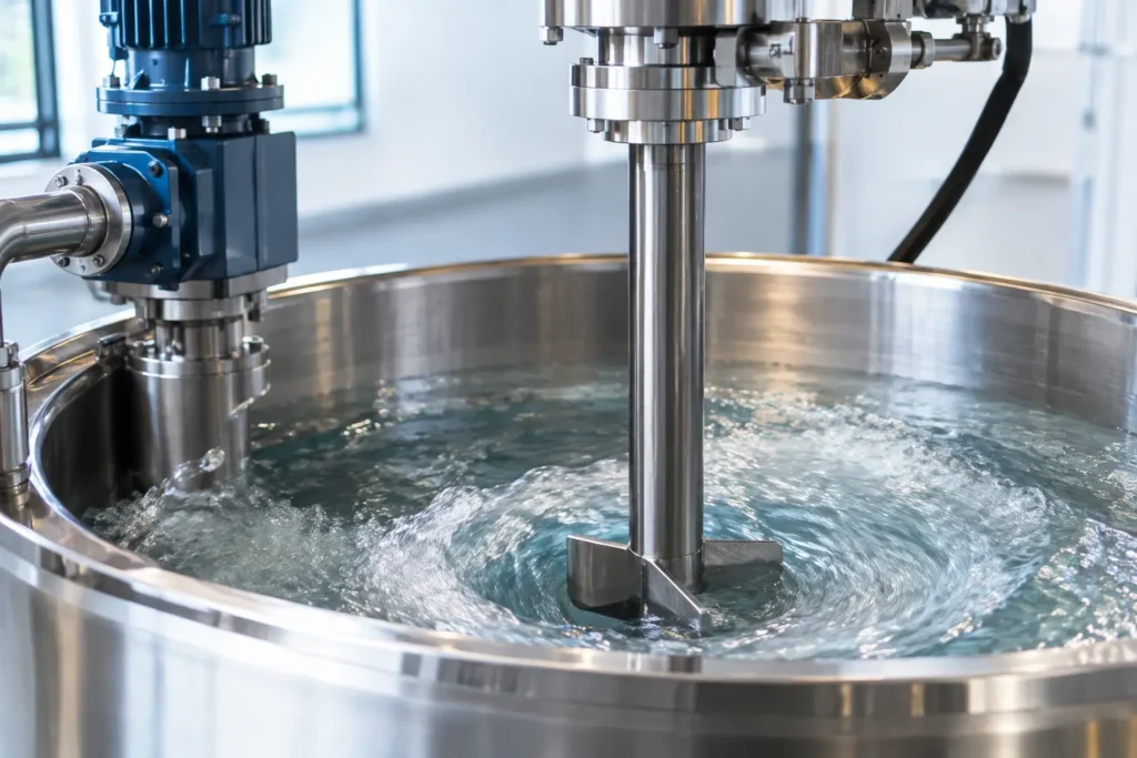
A tank mixer that suddenly sounds like gravel in the gearbox is not creating more shear. It may be damaging its impeller, shaft, seal, and product consistency. Mixer cavitation causes are usually traceable to local pressure falling below the liquid's vapor pressure at or near the impeller. The resulting vapor bubbles collapse as they move into higher-pressure regions, producing noise, vibration, pitting, and unstable mixing performance.
Cavitation is more than a maintenance nuisance. In chemical dosing, emulsification, polymer processing, wastewater treatment, and batch blending, it can change the effective pumping capacity of the impeller and leave zones of poor circulation. A reliable correction starts by separating true cavitation from air entrainment, mechanical vibration, and process conditions that simply exceed the mixer’s operating range.
What Cavitation Does Inside a Mixer
An impeller produces a pressure field as it rotates. On the low-pressure side of a blade, liquid pressure can drop sharply. If that local pressure falls below the fluid’s vapor pressure at operating temperature, vapor cavities form. When those cavities collapse, the energy is concentrated against nearby metal surfaces.
The familiar symptoms are a crackling or rattling sound, fluctuating motor load, rising vibration, reduced circulation, and roughened impeller surfaces. In severe service, blade edges can develop pits that further disrupt hydraulic performance. A mixer may still turn at its commanded speed while delivering less useful flow to the tank.
True cavitation is distinct from air entrainment, although the two often occur together. Air entrainment brings atmospheric gas into the liquid through a surface vortex, leaking suction line, or poorly managed addition point. Those air bubbles can cause noise, foam, density variation, and loss of impeller performance. Cavitation forms vapor from the process liquid itself because of a local pressure drop. The corrective action depends on identifying which condition is present.
The Main Mixer Cavitation Causes
Low liquid level and poor impeller submergence
Insufficient submergence is one of the most common causes in top-entry, portable, and side-entry tank mixers. When the liquid level approaches the impeller, surface effects reduce the static pressure available at the blade. The impeller can pull a vortex down from the surface, then operate in a mixture of liquid and vapor or air.
Minimum operating level should be established for every batch and maintained through the full operating cycle, not only at startup. This matters when a mixer runs while a vessel is being drained, when batch size changes, or when a level instrument is inaccurate. A nominally correct tank level can still be inadequate if the impeller is mounted too high or if an off-center mounting arrangement creates a deep local vortex.
Vortexing and air drawdown
A centered, vertical mixer in an unbaffled round tank is especially prone to vortexing. As rotational flow builds, the free surface forms a funnel. At high speed, that funnel can reach the impeller. Even before it does, the altered flow pattern may reduce pressure near the blade and draw air into the batch.
Baffles are often the most direct solution for low-viscosity turbulent mixing. Tank-mounted anti-vortex plates, an offset mixer location, or an angled shaft can also disrupt bulk rotation where baffles are impractical. These changes must be evaluated against cleaning requirements, tank geometry, solids suspension needs, and sanitary constraints. A sanitary process may favor an optimized off-center mounting position over permanent internal baffles.
Excessive speed or the wrong impeller duty
Higher rpm is not a universal cure for slow blending. Increasing speed increases blade-tip velocity and lowers local pressure on the suction side of the impeller. At some point, the additional speed drives cavitation, air entrainment, or excessive surface turbulence instead of improving bulk turnover.
An impeller selected for high shear may also be a poor choice for a large-volume blending duty. Rotor-stator heads, dispersers, and some hydrofoil geometries create intense local hydraulic conditions by design. They must be matched to fluid properties, liquid level, vessel dimensions, and intended shear rate. Conversely, a large, slower axial-flow impeller may move the same tank volume with lower tip speed and less cavitation risk.
Variable-frequency drives provide a practical diagnostic tool as well as operating flexibility. If noise and vibration begin at a repeatable speed threshold and diminish when rpm is reduced, the mixer may be approaching a cavitation or vortexing limit. That observation should lead to an engineering review, not an arbitrary permanent speed reduction that leaves the process under-mixed.
Elevated temperature and volatile fluids
Vapor pressure rises as liquid temperature rises. A mixer that operates quietly with cool water may cavitate when processing a heated solvent, hot cleaning solution, hydrocarbon blend, or temperature-sensitive chemical. The same mixer can therefore have very different limits across a heat-up, reaction, or cooling cycle.
Volatile components require additional attention because agitation can release dissolved gases and create vapor at locations of low pressure. Tank pressure also matters. Operating under vacuum or at a lower-than-expected headspace pressure reduces the margin before vapor formation. For closed vessels, review the complete process condition: temperature, absolute tank pressure, fluid composition, and the lowest anticipated liquid level.
High viscosity, non-Newtonian behavior, and poor circulation
Viscous fluids do not always cavitate in the same way as low-viscosity liquids, but viscosity can create the conditions that lead to unstable operation. Thick materials may form a rotating mass around the shaft, channel around the impeller, or leave stagnant regions that prevent normal circulation. Shear-thinning materials add another variable because their apparent viscosity changes near the impeller.
A mixer can appear adequately sized based on a single viscosity value yet produce poor flow in the actual process. Impeller diameter, blade design, clearance from the tank bottom and wall, shaft position, and multiple-impeller spacing all affect the outcome. In difficult rheology, a trial based on representative material or mixer simulation is usually more dependable than selecting equipment from horsepower alone.
Restrictions near the impeller
Internal coils, dip pipes, injection quills, level probes, support legs, and filter baskets can interfere with mixer inlet flow. If an obstruction sits too close to the impeller, it can create uneven pressure distribution, recirculation pockets, and turbulence that looks like cavitation. The problem may only appear after a tank modification or installation of new instrumentation.
Chemical injection deserves particular care. Injecting directly into an impeller’s low-pressure zone can cause flashing, gas release, or concentrated chemical exposure at the blade. A properly located injection quill should introduce the chemical where it disperses safely without disrupting the impeller’s intake flow. Material compatibility and injection velocity matter as much as physical placement.
How to Confirm the Problem Before Changing Equipment
Start with the operating record. Compare vibration, sound, motor amperage, tank level, temperature, pressure, and rpm at the time the issue occurs. Cavitation often tracks with a specific liquid level, speed, temperature, or batch phase. Mechanical faults such as bearing wear, bent shafts, loose mounts, and damaged gears may produce similar noise but will not necessarily correlate with process conditions.
Next, inspect the impeller during planned downtime. Cavitation damage commonly appears as localized pitting, often on blade surfaces exposed to the low-pressure side of flow. Look for polished areas, eroded edges, cracked coatings, and changes in blade profile. Also inspect for signs of surface vortexing, foam, or air bubbles in the batch.
A controlled speed test can help isolate the mechanism. Operate within safe process limits and document how the condition changes with rpm and liquid level. If adding level or reducing rpm immediately improves the condition, submergence and vortex control are likely contributors. If the symptom persists regardless of level but rises with shaft speed, investigate mechanical alignment and bearing condition alongside hydraulic causes.
Correct the Hydraulic Condition, Not Just the Noise
The right remedy may be as simple as enforcing a higher minimum liquid level or lowering mixer speed during fill and drain. In other cases, the tank needs baffles, a different mounting location, a larger lower-speed impeller, or a multi-impeller shaft arrangement. Heated or volatile service may require a revised operating envelope that accounts for temperature and vessel pressure.
Do not assume that heavier construction alone solves cavitation. A stronger shaft or upgraded alloy can tolerate damage longer, but it does not restore circulation quality or prevent vapor collapse. Material selection should follow the corrected hydraulic design. Stainless steel, specialty alloys, polymer-lined components, and sanitary finishes each have a place, but geometry and operating conditions come first.
For systems with injection, recirculation, or multiple tank internals, evaluate the mixer as part of the complete process. ProMixUSA engineers tank mixing, static mixing, and safe chemical injection equipment around actual fluid behavior, vessel constraints, and connection requirements. That application-level approach is especially valuable when a simple speed adjustment has not resolved the issue.
A mixer should run with controlled circulation, stable power draw, and enough hydraulic margin to handle normal operating variation. Establish those limits during specification or troubleshooting, document them for operators, and cavitation becomes a preventable process condition rather than an expensive surprise.