
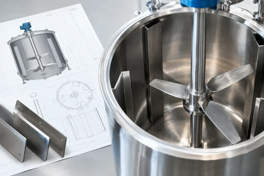
A tank can have the correct agitator, motor, and impeller yet still produce an inconsistent batch because the liquid is rotating as one mass. This tank baffle design guide addresses the vessel feature that interrupts that rotation, converts it into useful turbulence, and gives the impeller a stable mixing environment. For process engineers and plant teams, baffle selection is not a minor fabrication detail. It directly affects blend time, solids suspension, gas dispersion, heat transfer, motor load, and repeatability.
What tank baffles actually do
A baffle is a fixed vertical plate, strip, or formed internal surface installed near the tank wall. Its primary job is to resist tangential liquid flow. Without that resistance, a top-entry mixer commonly creates a vortex. The fluid spins around the vessel centerline, the surface drops near the shaft, and the impeller recirculates liquid rather than moving it through the full tank volume.
A visible vortex is not always proof of failed mixing, but it is often a warning. Deep vortexing can draw air into the batch, increase foaming, reduce pumping efficiency, and create poor circulation zones near the bottom or wall. In liquid-liquid blending, it may lengthen the time needed to reach a uniform concentration. In slurry service, it can leave solids settled outside the impeller's effective flow path.
Properly designed baffles break the rotating flow pattern and promote axial and radial circulation. The result is more useful energy from the same mixer. This is why baffling must be evaluated alongside impeller type, shaft location, operating speed, tank geometry, and fluid properties.
Start with the process, not a standard plate size
Four full-height baffles are a common starting point for a cylindrical tank with a centered top-entry mixer. That starting point is useful, but it is not a universal specification. A baffle arrangement that works in a low-viscosity water-like batch may be unsuitable for a viscous polymer solution, a sanitary food product, or a vessel with internal coils and a dished bottom.
Begin by defining what the mixer must accomplish. Blending miscible liquids, suspending solids, dispersing gas, promoting heat transfer, and emulsifying immiscible liquids have different flow demands. A process that requires extreme emulsification may need high-shear equipment in addition to vessel-scale circulation. Baffles improve bulk flow control, but they do not replace the shear generated by a rotor-stator or other high-shear device.
Fluid viscosity changes the design decision quickly. In turbulent, low-viscosity service, baffles are highly effective at eliminating swirl and increasing power draw to a productive level. As viscosity rises and flow becomes laminar, the liquid is less likely to form a deep vortex. Wide wall clearances, helical ribbon impellers, anchor agitators, or close-clearance mixer designs may become more relevant than conventional flat baffles.
The tank itself also matters. Diameter-to-liquid-height ratio, bottom profile, maximum and minimum liquid level, nozzles, coils, dip pipes, level instruments, and manway access all affect available space. A baffle drawing should never be finalized before the internal vessel layout is known.
Core geometry for a tank baffle design
For a conventional round tank, a typical baffle width is approximately one-twelfth to one-tenth of the tank diameter. In practical terms, a 48-inch diameter vessel may use baffles roughly 4 to 5 inches wide. Four equally spaced baffles are common because they provide consistent resistance around the vessel without creating an excessive number of internal obstructions.
Baffles are generally installed vertically and extend through most of the working liquid depth. They should remain effective at the normal operating level, not merely at a full tank condition. If batches run at widely different fill volumes, the design should consider whether partial-height baffles, multiple impeller elevations, or a different mixer configuration will maintain circulation across that range.
A small gap between the baffle and vessel wall is often specified. This clearance reduces stagnant material behind the baffle and can improve cleanability. It is especially valuable where crystallization, solids buildup, or viscous residue is a concern. The gap must be large enough to avoid trapping product but small enough that liquid does not simply bypass the baffle with little flow disruption.
Bottom clearance is equally important. Extending a baffle directly into a dished bottom or close to a bottom outlet can create a cleaning challenge and interfere with drainage. The final lower termination should account for the vessel contour, outlet location, and any need for complete batch recovery.
Flat, angled, and formed baffles
Flat plate baffles are the standard choice for many chemical, water-treatment, and general industrial applications. They are direct, economical, and effective when fabricated from the correct material. Their main trade-off is cleaning access. Product can accumulate at welds, behind wall-mounted plates, or in narrow clearances when the process handles sticky or solids-bearing material.
Angled baffles and formed baffle sections can reduce buildup and may be selected for specific circulation patterns or fabrication constraints. In sanitary processing, designs often favor smooth surfaces, continuous welds, drainable geometry, and access for clean-in-place coverage. A baffle that improves mixing but cannot be cleaned or inspected reliably is not a production-ready solution.
Account for mixer power and mechanical loading
Baffles increase resistance to flow. That is their purpose, but it also means they can materially increase agitator power demand. A mixer sized for an unbaffled tank may overload when four full-width baffles are installed. Motor horsepower, gearbox rating, shaft diameter, impeller blade design, and seal selection should all be checked using the baffled operating case.
This is particularly critical when a plant is upgrading an existing tank. Adding baffles can correct vortexing, yet the modification may reveal that the installed drive lacks sufficient torque. Conversely, removing baffles during a vessel replacement can reduce mixing quality even though the mixer appears to run normally.
Mechanical design also deserves attention. Baffles must withstand process velocity, vibration, thermal cycling, vacuum conditions where applicable, and forces during cleaning. Thin plates with poor support can fatigue at weld points. Long baffles may require stiffeners, formed edges, or engineered supports, but those features should not create unnecessary product hold-up zones.
Select materials for the actual chemical and cleaning conditions
Material selection should be based on the fluid, concentration, temperature, pressure, cleaning chemicals, and contamination requirements. Stainless steel is widely used for sanitary, food, beverage, pharmaceutical, and many chemical services. However, chloride exposure, strong acids, caustics, and elevated temperatures can change the alloy recommendation.
For corrosive chemical injection or water-treatment applications, PVC, CPVC, PVDF, PFA-lined construction, or specialty alloys may offer a better service life than standard stainless. The right answer depends on the full exposure profile, including intermittent cleanouts and upset conditions. A baffle material that survives the normal batch but degrades during routine cleaning is an avoidable maintenance problem.
Surface finish also affects performance beyond appearance. Smooth finishes reduce adhesion and improve cleanability. Sanitary vessels may require controlled weld quality and finish requirements around every baffle attachment. In abrasive slurry service, thicker materials or wear-resistant construction may be justified, particularly near high-velocity discharge zones.
When conventional baffles are not the best answer
Some applications benefit from alternatives. An off-center mixer or an angled shaft can reduce vortex formation in smaller tanks where wall-mounted baffles are impractical. Portable mixers often use this approach because the vessel may be temporary, open-top, or used for multiple products.
Square and rectangular tanks have natural corners that disrupt circular flow, so they may need fewer baffles or none at all. Still, corners can become low-flow regions, especially with solids or viscous fluids. Mixer position and impeller pumping direction must be evaluated rather than assuming the tank shape solves the problem.
For highly viscous batches, close-clearance impellers, scraped-wall designs, and carefully selected axial flow impellers can deliver more value than adding large baffles. For inline dosing or continuous blending, a static mixer and injection quill may provide controlled mixing without relying on a stirred vessel. ProMixUSA engineers both vessel mixing and flow-conditioning equipment, allowing the mixing method to follow the process requirement instead of a catalog default.
Validate the design before fabrication
The strongest baffle design is one that has been reviewed as part of the complete mixing system. Confirm the operating volume range, product rheology, impeller diameter and elevation, shaft speed, drive power, internal obstructions, cleanability needs, and material compatibility. For difficult services, mixer simulation can identify recirculation zones, surface vortex behavior, solids settling risk, and gas entrainment before equipment reaches the plant.
Commissioning should also include process-based acceptance criteria. Watch batch uniformity, mixing time, surface behavior, amperage, temperature distribution, and any accumulation behind baffles. A mixer that runs smoothly is not necessarily delivering the required blend quality.
The best tank baffle design is not the largest plate that fits inside the vessel. It is the geometry that gives the impeller a controlled flow field, respects cleaning and maintenance realities, and delivers repeatable batch performance shift after shift.