
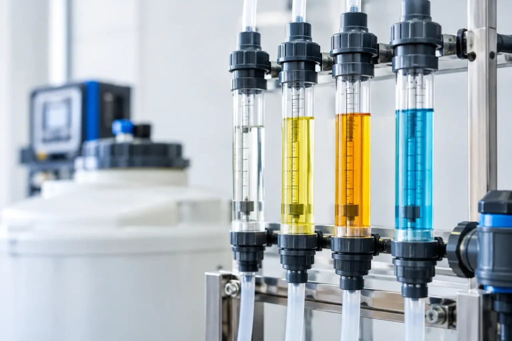
A chemical metering pump can be set to a calculated stroke length and speed, then still deliver the wrong dose. Suction conditions change, check valves wear, fluid viscosity shifts, and calibration drifts over time. Calibration columns provide the direct field verification that turns a pump setting into a measured chemical feed rate.
For water and wastewater treatment, cooling towers, boiler feed, chemical manufacturing, mining, pulp and paper, and process skids, that measurement has immediate consequences. An underfeed can compromise treatment performance or product quality. An overfeed raises chemical costs, creates safety exposure, and can put discharge or process limits at risk. A properly selected calibration column gives operators a simple, repeatable way to confirm actual pump output under operating conditions.
What Calibration Columns Measure
A calibration column, also called a calibration cylinder or calibration pot, is a transparent graduated vessel installed on the suction side of a chemical metering pump. During a test, the operator isolates the normal chemical supply, fills the column to a known graduation, and runs the pump for a timed interval. The change in liquid volume establishes the actual flow rate.
The basic calculation is straightforward:
Actual feed rate = volume displaced ÷ test time
If a pump draws 500 mL from the column in 60 seconds, its verified output is 500 mL per minute. That result can be converted to gallons per hour, liters per hour, pounds per day, or the plant's preferred control basis. More importantly, it can be compared with the required dose and the pump's expected capacity.
The column does not correct a pumping problem by itself. It exposes the difference between intended and delivered flow so the operator can adjust pump speed or stroke, inspect check valves, remove air, correct suction restrictions, or review fluid properties. That is why calibration equipment belongs in the process control strategy, not as an afterthought during startup.
Why Actual Pump Output Changes
Positive displacement metering pumps are designed for repeatability, but repeatability depends on the complete pumping system. A new pump tested with water at ambient temperature may perform differently after it is placed into service with a viscous polymer, sodium hypochlorite, acid, caustic, or a solution containing entrained gas.
Suction lift is a common source of error. A pump that must pull chemical from a low tank elevation can lose volumetric efficiency, especially with higher-viscosity fluids. Long suction piping, undersized tubing, plugged strainers, partially closed valves, and inadequate net positive suction head can all restrict the pump inlet. A calibration test will show the result even when the pump appears to be operating normally.
Discharge pressure matters as well. Higher backpressure can affect delivered volume, depending on pump type, diaphragm condition, relief arrangement, and check-valve performance. Chemical temperature and specific gravity may change from batch to batch. For that reason, the most useful calibration is performed with the system in its normal operating state, not only during a clean-water shop test.
Selecting Calibration Columns for the Application
Column capacity should match the pump's expected feed rate and the test duration needed for a readable result. A very large column used with a low-flow pump produces a small level change that is hard to read accurately. A column that is too small may empty before a meaningful timed test is complete.
A practical selection balances resolution with operating convenience. The volume displaced during the test should span enough graduations to minimize reading error, while leaving adequate fluid in the column to avoid pulling air into the pump. For low-output metering pumps, a smaller-diameter column with fine graduations often gives better accuracy. Higher-flow chemical feed systems generally require larger capacities and connections sized to prevent suction restriction.
Material compatibility is equally important. Acrylic is widely used because it provides excellent visibility and clear graduations, but it is not appropriate for every chemical, temperature, or pressure condition. PVC and CPVC components are common in many water-treatment duties. PVDF offers stronger resistance for demanding chemical service, while specialty materials may be required for aggressive acids, solvents, oxidizers, or high-purity applications.
The complete wetted assembly must be evaluated, not just the tube. That includes valves, seals, fittings, tubing, sight-column connections, and any mounting hardware exposed to spills or vapors. A chemically compatible column with an incompatible valve seal remains a failure point.
Connection and valve configuration
Most installations use a three-valve arrangement that lets the operator switch safely between the bulk chemical source and the calibration column. In normal operation, the pump draws from the storage tank. During calibration, the storage-tank suction valve is closed and the calibration-column valve is opened. After the timed drawdown, the system is returned to its normal suction path.
The valve layout must prevent accidental isolation of the pump suction or unintended chemical transfer. Clear valve tags, logical handle orientation, and a written calibration sequence matter as much as the physical hardware. For hazardous chemicals, secondary containment, splash protection, ventilation, and access for appropriate personal protective equipment should be part of the equipment layout.
Installation Details That Protect Accuracy
Calibration columns are suction-side instruments. They should be mounted vertically, where the graduations are easy to read and where operators can safely observe the liquid level. A level, supported installation prevents false readings and reduces stress on transparent tubing and threaded connections.
Keep the suction line between the column and pump as short and direct as practical. Avoid unnecessary elbows, high points that trap air, and restrictive fittings. The suction piping must be sized for the pump's flow rate, fluid viscosity, and suction conditions. A calibration column cannot compensate for a poorly engineered suction line.
For applications with strong chemical fumes or crystallization risk, consider the accessibility of the column before finalizing the skid or wall-mounted arrangement. Operators need room to operate valves, read the scale, clean residue, and perform maintenance without reaching across discharge piping or electrical equipment. On complete chemical injection skids, placing the column within the operator's normal line of sight improves the likelihood that routine verification actually occurs.
A Field Method for Repeatable Calibration
A consistent procedure produces data that can be trusted and trended. Before testing, confirm that the chemical tank level, pump setting, discharge pressure, and process conditions are stable. Prime the pump and remove air from the suction path. Air bubbles compress and expand, which can make a volumetric test look inconsistent even when the pump is mechanically sound.
Fill the column above the planned starting graduation. Switch the suction source to the column, allow the fluid level to stabilize, and record the initial volume. Run the pump for a measured period long enough to create a clear volume change. Record the final volume, calculate the flow rate, and repeat the test if the result is unexpected.
Avoid judging pump performance from one short test. Running two or three tests at the same setting is often enough to reveal whether the issue is random reading variation or a repeatable delivery problem. If output differs significantly from the target, inspect the system before simply increasing stroke or speed. A setting adjustment may hide a blocked suction strainer, worn valve seat, damaged diaphragm, or loss of suction head.
For critical dosing applications, document the date, pump identification, chemical, pump setting, suction condition, discharge pressure, test duration, actual output, and operator. That record supports preventive maintenance, compliance reporting, and faster troubleshooting when treatment performance shifts.
Common Calibration Errors
The most frequent error is testing under conditions that do not resemble normal service. A pump calibrated with water may not feed the same volume of a thick or gas-releasing chemical. Testing with the normal chemical and normal process backpressure delivers more useful results.
Operators can also introduce error by starting a timer before the liquid level stabilizes, reading the meniscus from an angle, or selecting too short a drawdown interval. Transparent columns make measurement simple, but they do not eliminate the need for disciplined technique. Read at eye level and use a test interval appropriate to the graduation resolution.
Another issue is ignoring system changes after calibration. Replacing a pump head, changing chemical concentration, cleaning a strainer, switching suppliers, or changing discharge pressure can all alter actual feed. Recalibration should follow any material process change, not only a scheduled maintenance interval.
Calibration as Part of a Complete Injection System
A calibration column verifies how much chemical reaches the pump inlet. It does not prove that the chemical is mixed effectively after injection. For reliable treatment or reaction performance, the injection point, quill design, static mixer, retention time, and flow conditions must work together.
This is especially relevant where concentrated chemicals enter high-flow process lines. A verified metering rate combined with a correctly positioned injection quill and properly sized static mixer creates controlled, repeatable distribution. Without that downstream mixing performance, accurate pump output may still produce poor process results.
ProMixUSA supplies calibration columns and chemical injection equipment for systems that need practical field verification alongside engineered flow control and mixing performance. The right column is not simply a clear tube with graduations. It is a service-specific component selected around chemical compatibility, pump capacity, operator safety, connection requirements, and the realities of plant operation.
When dosing affects compliance, corrosion control, disinfection, product consistency, or chemical spend, measure the output instead of assuming it. A well-specified calibration column gives the operating team a clear number to act on before a small feed-rate error becomes a process problem.