
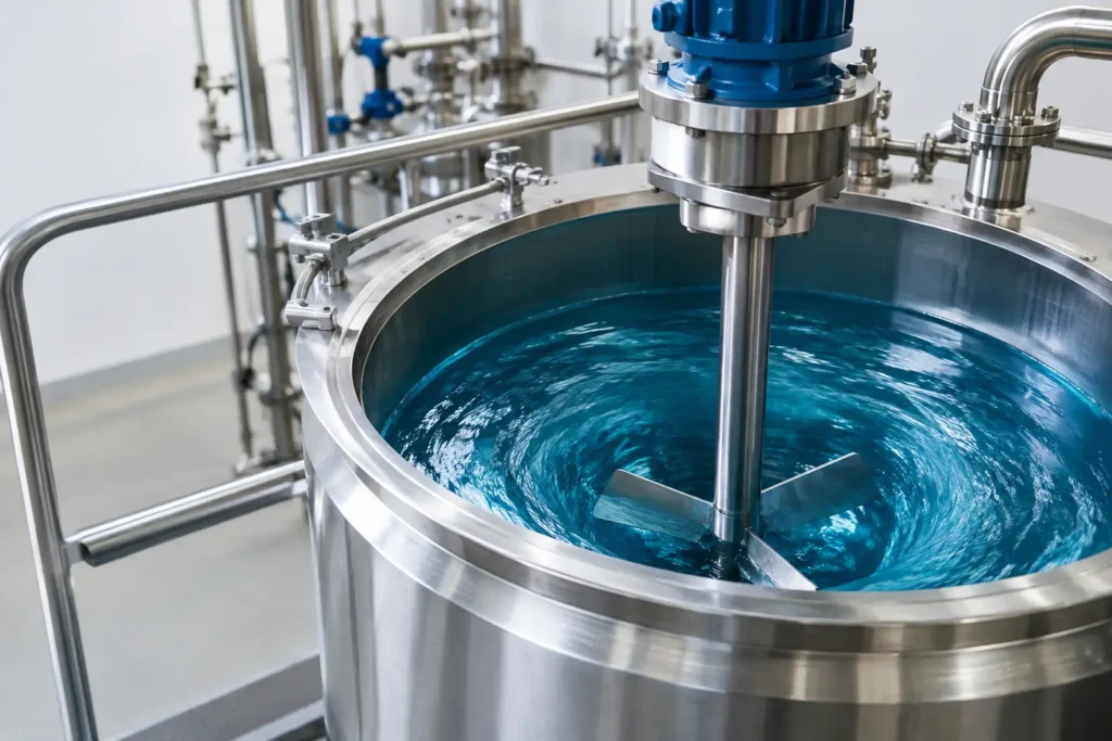
A deep surface funnel in an agitated vessel may look like evidence of vigorous mixing. In many industrial processes, it is evidence that too much mixer energy is being converted into liquid rotation instead of useful bulk circulation. Knowing how to prevent tank vortexing protects batch consistency, reduces air entrainment, and helps the mixer deliver the flow pattern the process actually requires.
Tank vortexing is common in low-viscosity liquids, especially when a centered top-entry mixer operates at high speed in a smooth, round tank. The liquid begins to rotate as a mass. Centrifugal force pushes it up the vessel wall and pulls the surface downward at the center, creating the familiar vortex. Left unaddressed, that rotating flow can reduce axial turnover, pull air into the batch, and create operating problems far beyond the tank surface.
Why Tank Vortexing Creates Process Problems
A vortex is not automatically a failure. Some applications intentionally use controlled surface drawdown. However, uncontrolled vortexing is usually a warning that the vessel, impeller, and operating speed are not working together effectively.
The most immediate concern is air entrainment. Once the vortex reaches the impeller zone, air can be pulled into the liquid as bubbles. In chemical blending, this can alter density, reaction behavior, or analytical results. In coatings, polymers, adhesives, food products, and emulsions, it can produce foam, pinholes, oxidation, inconsistent viscosity, or unacceptable finished-product appearance.
Vortexing also wastes energy. A mixer can consume substantial horsepower while primarily spinning the entire batch instead of driving top-to-bottom circulation. Solids may settle in dead zones, additives may remain poorly dispersed, and heating or cooling performance can suffer when the bulk liquid is not turning over as intended.
For sensitive or hazardous service, surface instability creates additional concerns. Volatile liquids can release more vapor. Corrosive or reactive chemicals can splash or foam. A process that depends on repeatable chemical dosing cannot afford variable entrainment and inconsistent residence time.
How to Prevent Tank Vortexing at the Source
The best solution depends on liquid viscosity, tank geometry, fill level, impeller type, required shear, and whether the operation is batch, semi-batch, or continuous. The goal is not simply to eliminate the visible funnel. It is to redirect mixer power into the circulation, dispersion, and shear duties that matter to the process.
Install Baffles to Break Rotational Flow
Baffles are the most direct and reliable method for stopping bulk liquid rotation in a cylindrical tank. Vertical plates mounted along the tank wall interrupt tangential flow and convert rotational motion into turbulence and axial circulation. With baffles installed, an axial-flow impeller can push liquid downward or upward while the vessel geometry resists the tendency of the entire batch to spin.
Standard baffled vessels commonly use four equally spaced baffles. Their width, wall clearance, and length should be selected for the vessel diameter, fluid properties, cleanability requirements, and fabrication constraints. A baffle that is too narrow may have limited effect. One that is oversized or poorly located can create stagnant pockets, complicate cleaning, or interfere with internal components.
Full-height flat baffles are proven in many chemical and water-treatment applications, but they are not the only option. For sanitary service, where clean-in-place coverage and drainability are priorities, designers may use flush-mounted baffles, formed wall features, or alternative vessel geometry. In corrosive service, baffle material selection must match the chemical environment just as carefully as the mixer wetted parts.
Offset or Angle the Mixer Shaft
When conventional baffles are impractical, off-center mixer placement is often effective. Moving the shaft away from the tank centerline disrupts the symmetry that allows the liquid to rotate freely. Tilting the shaft can produce a similar result by directing flow asymmetrically through the vessel.
This approach is especially useful for portable mixers, temporary batches, tanks with restricted access, and vessels where internal baffles would hinder cleaning or product removal. It is not a universal substitute for baffles. Offset mounting changes loading on the shaft and drive, and the flow pattern must still reach the tank bottom, corners, and liquid surface. The mixer support structure and vessel nozzle must be engineered for the resulting mechanical loads.
A slight offset or angle can be enough in some low-viscosity services. For high-speed blending or large-diameter tanks, the process may still need baffles, a revised impeller, or lower operating speed.
Match Impeller Geometry to the Mixing Duty
Impeller selection has a major effect on vortex formation. Radial-flow turbines tend to discharge liquid outward from the blade tips and can create high local shear, but they may also contribute to tangential rotation when applied without adequate flow control. Axial-flow impellers, including pitched-blade turbines and hydrofoil designs, move liquid vertically through the tank and are often preferred when bulk circulation is the primary requirement.
The correct answer depends on the duty. Blending miscible liquids, suspending solids, dispersing gas, emulsifying immiscible phases, and maintaining heat transfer do not demand the same hydraulic profile. A high-shear mixer may be necessary for droplet-size reduction, but it should not be selected solely because it can create visible surface motion. Conversely, a large, slow axial impeller may provide excellent turnover with less air drawdown than a small, fast impeller.
Impeller diameter matters as much as blade style. Larger impellers generally produce greater pumping capacity at lower rotational speed. That often reduces vortexing while maintaining or improving bulk circulation. Smaller impellers operating at elevated RPM can generate concentrated shear and strong surface rotation, particularly in unbaffled tanks.
Reduce Speed Without Giving Up Mixing Performance
Reducing RPM is the simplest operating change, but it must be evaluated against the actual process target. If the vortex disappears but solids settle, temperature becomes nonuniform, or additive dispersion slows excessively, the mixer is no longer meeting its duty.
Variable-frequency drives are valuable because they allow operators to establish a stable speed range for each product and fill level. A batch may need higher speed during initial powder wet-out, then lower speed once the material is incorporated. Similarly, a vessel near minimum operating volume may vortex at a speed that is stable at normal fill level.
A more efficient correction is often to reduce speed while increasing impeller diameter or changing the impeller design. This shifts the system toward controlled pumping rather than high-speed swirling. It can also reduce mechanical stress, noise, and power demand.
Account for Tank Geometry and Liquid Level
A round, vertical vessel naturally promotes rotational flow. Flat-bottom tanks, dished-bottom tanks, conical bottoms, and rectangular vessels each respond differently to mixer placement and impeller discharge. Internal coils, dip tubes, level instruments, and injection quills can either help disrupt rotation or create shadow areas that require additional attention.
Liquid level is equally important. A mixer that performs well at 80 percent full may create severe drawdown at 30 percent full because the impeller is closer to the free surface and the flow path has changed. Specify the normal, minimum, and maximum operating levels when sizing equipment. Designing only for full-tank operation is a frequent cause of unpredictable mixing performance.
For tall vessels, multiple impellers on a common shaft may be required to maintain circulation across the full liquid height. For wide tanks, a larger-diameter impeller or multiple mixers may be more effective than pushing a single small impeller to excessive speed. The right configuration is application-specific, not a catalog shortcut.
Control Air Entrainment During Additions and Injection
Vortexing becomes more troublesome when powders, gases, or liquid additives are introduced near the surface. An open vortex can pull an addition stream directly into a high-velocity zone, causing foam, fisheyes, agglomerates, or localized overconcentration.
Introduce chemicals where the bulk liquid has reliable circulation, not simply where installation is convenient. A properly located injection quill can place a reagent into the flowing stream below the surface, reducing splashback and improving distribution. In recirculation systems, an inline static mixer can complete blending in the pipe and reduce reliance on aggressive tank agitation alone.
For challenging liquid-liquid emulsification or reactive injection, combining a tank mixer with an engineered injection point and inline mixing stage can provide more repeatable results than increasing tank-mixer speed. This is particularly valuable when air entrainment, dosage accuracy, or shear exposure must be tightly controlled.
Validate the Correction Under Real Operating Conditions
Do not judge vortex control by appearance alone. A calm surface does not prove that the batch is homogeneous, and a minor surface depression may be acceptable if there is no air entrainment and process results remain consistent. Confirm performance using the criteria that govern the operation: blend time, concentration uniformity, solids suspension, temperature profile, particle or droplet size, foam level, and batch-to-batch repeatability.
Mixer simulation and process testing are useful when the tank contains non-Newtonian fluids, changing viscosities, multiple phases, or unusual internals. These applications often require a closer look at flow patterns before modifying a vessel or committing to a new mixer. ProMixUSA helps process teams evaluate impeller technology, mounting arrangements, materials, and complete mixing configurations for difficult service conditions.
The practical target is controlled circulation, not maximum surface motion. When the impeller, vessel geometry, operating speed, and injection strategy are aligned, the tank becomes quieter, cleaner, and far more predictable where it counts: in the finished batch.