
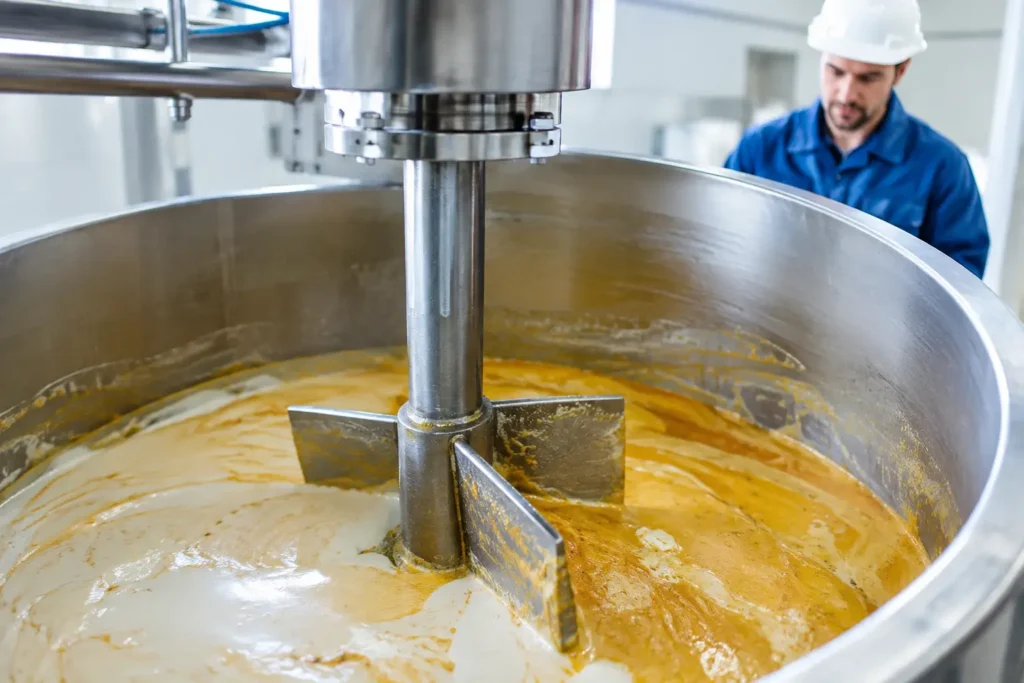
A batch can look uniform at the tank surface and still fail quality testing hours later. Concentration gradients, undispersed additives, separated phases, and inconsistent viscosity often point to the same root problem: poor blending causes are usually process-design issues, not simply a lack of mixer horsepower.
For plant teams, the practical question is not whether a mixer is turning. It is whether the equipment is creating the circulation, shear, residence time, and additive distribution the application requires. Finding the answer requires looking at the fluid, vessel, piping, injection point, and operating window as one system.
Poor Blending Causes Start With Flow Behavior
The same mixer can perform very differently when fluid viscosity, density, temperature, or batch volume changes. A low-viscosity liquid may circulate readily with a conventional axial-flow impeller. A high-viscosity material may rotate with the same impeller while most of the vessel remains stagnant.
Flow regime matters immediately. In turbulent service, eddies help distribute material across the vessel or pipe. In laminar service, the fluid moves in more orderly layers, making radial and axial circulation far more difficult. High-viscosity polymers, gels, slurries, pastes, and temperature-sensitive products commonly need equipment designed to sweep a larger working volume rather than relying on localized turbulence.
Density differences can create another problem. A heavy chemical injected into a lighter carrier may sink before it disperses. A light hydrocarbon, oil, or gas phase may rise and short-circuit to the outlet. When solids settle, a top-mounted mixer may not reach the material accumulated near the vessel floor. These are hydraulic realities that must be addressed with impeller geometry, mixer position, baffles, injection location, and operating speed.
Incorrect Mixer Selection or Sizing
Motor power alone does not define mixing performance. A high-horsepower mixer with the wrong impeller can create excessive surface turbulence while leaving lower vessel zones poorly circulated. Conversely, an undersized unit may never generate enough fluid movement to suspend solids or break up concentration layers.
Impeller type must match the objective. Axial-flow impellers are often selected for bulk circulation, blending, and solids suspension. Radial-flow designs can provide stronger local shear for gas dispersion and certain emulsification duties. High-shear mixers are appropriate when droplet or particle size reduction is required, but they are not automatically the best choice for moving the full contents of a large tank.
Mixer diameter, rotational speed, blade clearance, and shaft length must work together. An impeller placed too close to the liquid surface may pull air into the product. One mounted too high above the tank bottom can leave settled solids untouched. In tall vessels, a single impeller may not provide adequate circulation from top to bottom, making multiple impellers or a different mounting arrangement necessary.
A side-entry mixer can be highly effective for large storage tanks and bulk blending, particularly where tank geometry supports broad circulation. Portable mixers offer flexibility for intermittent operations, but their performance depends on correct placement and sufficient reach. The right configuration depends on the process duty, not on which mixer style is easiest to install.
Vessel Geometry Creates Dead Zones
A mixer does not operate in open space. Tank diameter, liquid height, bottom shape, nozzles, coils, internal supports, and baffles all influence the resulting flow pattern. A vessel designed for storage is not always suitable for demanding blending or dispersion.
Unbaffled cylindrical tanks often develop a vortex. While a visible vortex may appear active, it can waste energy by spinning the entire liquid mass rather than forcing productive top-to-bottom circulation. It can also entrain air, creating foaming, oxidation, inaccurate density readings, or pump cavitation downstream. Properly sized baffles interrupt rotational flow and direct energy into mixing.
Dead zones commonly form behind internal coils, around supports, beneath dished or cone bottoms, and in oversized tanks operating at low liquid level. Batch plants should also account for minimum and maximum fill volumes. A mixer that performs well at 80 percent full may lose effective immersion or circulation at 30 percent full.
For difficult tank geometry, engineering review should include actual dimensions, internals, operating level, fluid properties, and required batch time. Computational fluid dynamics and mixer simulation can be valuable when a process cannot tolerate expensive field trial-and-error.
Poor Injection Location Can Defeat a Good Mixer
Chemical injection is frequently treated as a piping detail, but it directly affects blending quality. Introducing a concentrated reagent near a tank wall, in a low-velocity pipe section, or immediately upstream of an elbow can create localized overconcentration, deposition, corrosion, or incomplete reaction.
In continuous processes, the injection point should give the additive enough downstream residence time and energy to disperse before sampling, reaction, filtration, or final use. The correct location may be upstream of a static mixer, at a high-velocity zone, or through an injection quill positioned in the center of the process stream.
Injection quill design matters as much as location. The quill must withstand process pressure, vibration, chemical exposure, and potential backflow while delivering the chemical into the active flow zone. Retractable quills are useful where service access and isolation are required. Fixed designs may be appropriate for stable, dedicated applications. Material selection must address compatibility with both the injected chemical and the process fluid.
Static Mixer Design and Flow Conditions
An inline static mixer can provide repeatable mixing without a motor, but only when the element geometry, pipe size, pressure-drop allowance, and flow range are selected correctly. Static elements divide and redirect the stream repeatedly, creating controlled mixing as fluid passes through the assembly.
Poor results occur when flow is too low, the mixer is too short for the required blend quality, or the installed unit does not match the viscosity and flow regime. A design that works efficiently in turbulent water-like service may need substantially more elements for viscous, laminar-flow materials. Pressure drop is the trade-off. Increasing element count often improves homogeneity, but it also increases pumping requirements.
Maldistribution upstream can also limit static mixer performance. Partially open valves, asymmetric fittings, reducers, elbows close to the mixer inlet, and uneven multiphase flow can send an already distorted profile into the elements. A complete static mixing system may require upstream flow conditioning, a properly designed injection assembly, and downstream sampling at a representative location.
Operating Changes Often Explain Inconsistent Batches
When blending quality changes after years of acceptable operation, the equipment may not be the only suspect. Raw-material properties can drift between suppliers or lots. Temperature can alter viscosity significantly. A new cleaning procedure may leave residual water or cleaning agent. A production increase may reduce residence time below the point needed for complete blending.
Mechanical condition deserves equal attention. Worn impellers, bent shafts, damaged mixer elements, failing bearings, slipping belts, incorrect rotation, and degraded seals can all reduce performance. In static systems, fouling or deposits can change flow area and pressure drop while creating bypass channels that reduce effective mixing.
A useful troubleshooting sequence starts with process data: actual flow rate, temperature, viscosity, density, batch volume, mixer speed, motor load, pressure drop, and additive feed rate. Compare those values with the original design basis rather than relying on operator observation alone. Then inspect physical equipment condition and verify that sampling is being performed at a location and time that represent the blended product.
Specify for the Required Result
The phrase “good mixing” is too vague for equipment specification. Define the result in measurable terms: concentration uniformity, droplet size, particle size, solids suspension, blend time, reaction conversion, heat-transfer rate, or pH consistency. The requirement determines the appropriate level of shear and the acceptable trade-offs in energy use, pressure drop, and equipment complexity.
Material construction also belongs in the specification. Stainless steel may suit many process fluids, while PVC, CPVC, PVDF, PFA, lined components, sanitary finishes, or specialty alloys may be necessary for corrosive chemicals, high-purity service, or aggressive temperatures. Connection type, cleanability, seal design, and maintenance access affect long-term reliability as much as the mixing mechanism.
ProMixUSA engineers static mixers, mechanical mixers, injection quills, and complete mixing systems around real operating conditions, including difficult viscosities, corrosive media, restricted layouts, and changing process demands. The most effective correction is rarely a larger motor or a longer pipe run. It is a system designed to produce a repeatable result.
When batch quality begins to drift, treat it as process evidence. A careful review of flow behavior, injection method, equipment condition, and operating data can turn an unpredictable blend into a controlled, dependable operation.